


Table of Contents
Objectives
MiniZed TTC HW design Lab 9 is the final class for my MiniZed training path. I am going to review AMD Vivado HW flow on how to create Lab 9 from scratch.
Motivation of the blog
AMD Vivado ML tool is a very complex tool for a hobbyist to use. There are more than 63 user guides, 20 tutorials, 17 customer training and other materials from AMD website as this.

I am pretty sure many of readers who would like to build Lab 9 Vivado HW project from scratch, however, the process of the building might not go as smoothly as expected. So I would like to share my training process to build Lab 9 from scratch and point out some tips as well.
Build Lab 9 Vivado HW Project
Let us start the build from Lab 7 HW design, since most of trainers building Lab 7 from scratch under Vivado IP package flow. If you did not read Avnet training material yet, please read MiniZed+TTC+ZynqHW+Labs_2021_1: Lab 01 and Lab07 (Ref[1]). So I will not repeat the procedures to get Lab 7 done from scratch here. Readers can build a simple Zynq HW project from Vivado project flow under Lab 01 and add a user IP into Zynq SoC system from Lab07. Next we will add Vivado AXI IIC ip, AXI gpio ip, bluetooth UART and user VHDL module into MiniZed block design(BD) canvas.
1. Add AXI IPs
Lab 9 needs 3 IIC IPs and 2 GPIO IPs at PL for general purpose HW peripherals.
. GPIO0 is for MiniZed onboard LED(D8 green),
. GPIO1 is for onboard switch(SW1 and ARDUINO_A5)).
. IIC0: Arduino I2C
. IIC1: PMOD 1
. IIC2: PMOD2
1.1 Adding AXI IIC IPs
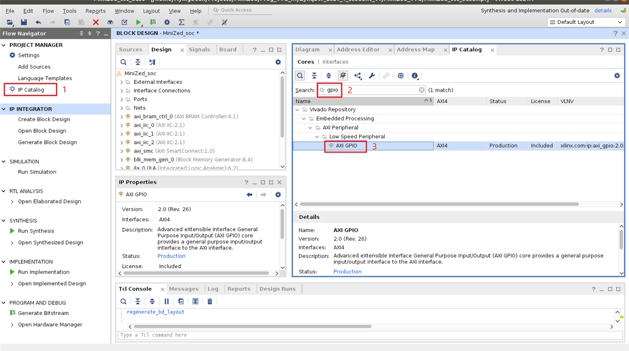
1.2 Add GPIO IPs
| {gallery}Add AXI GPIO IPs |
|---|
|
Select GPIO IP |
|
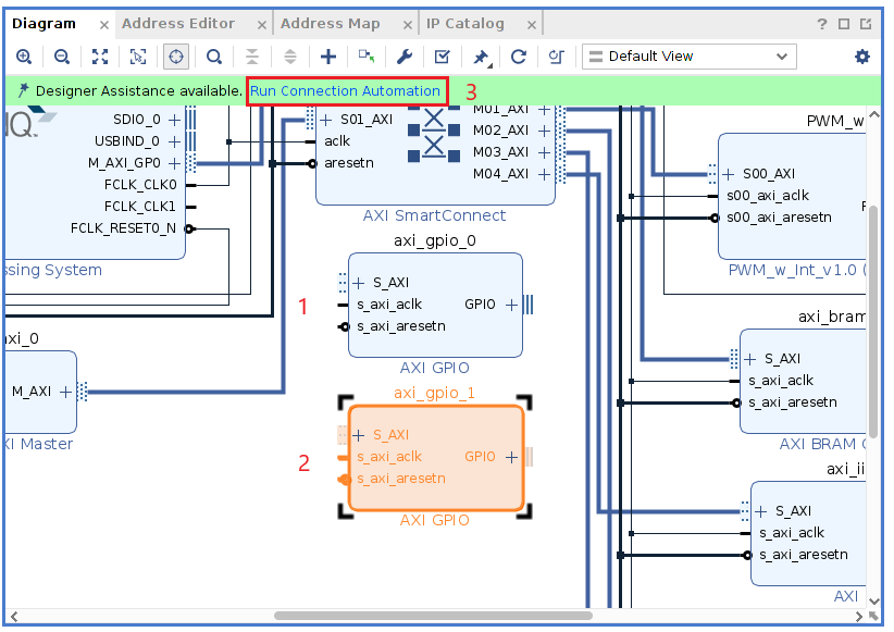
Add AXI GPIO IPs into BD Canvas |
|
Auto Connection of AXI GPIO IPs |

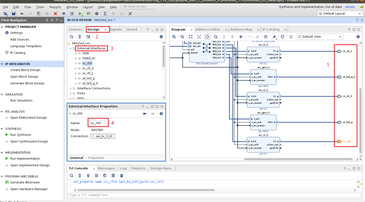
Tips:
Updating external pin names from BD->Design->External Interface Properties as below. It is easy and reliable way to update pin naming under Vivado project flow.
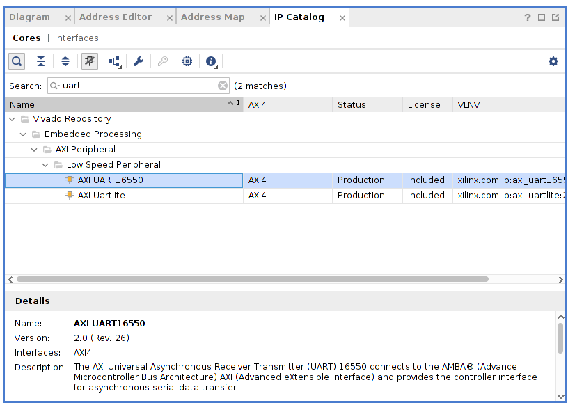
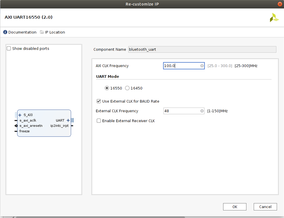
1.3 Add Bluetooth UART IPs
| {gallery}Add Bluetooth UART IP |
|---|
|
Search AXI UART16550 IP |
|
Configure Bluetooth UART IP |
2.Add User VHDL File into Block Design
We need to add wireless_mgr_0.vhd file into BD canvas as this styel. How can we do it at Vivado GUI tool chain?
Here is the VHDL source code provided by Avnet.
----------------------------------------------------------------------------------
-- Company:
-- Engineer:
--
-- Create Date: 09/14/2016 06:02:58 PM
-- Design Name:
-- Module Name: wireless_mgr - Behavioral
-- Project Name:
-- Target Devices:
-- Tool Versions:
-- Description:
--
-- Dependencies:
--
-- Revision:
-- Revision 0.01 - File Created
-- Additional Comments:
--
----------------------------------------------------------------------------------


library IEEE;
use IEEE.STD_LOGIC_1164.ALL;

-- Uncomment the following library declaration if using
-- arithmetic functions with Signed or Unsigned values
--use IEEE.NUMERIC_STD.ALL;
library IEEE;

use IEEE.std_logic_1164.all;
use IEEE.STD_LOGIC_UNSIGNED.all;
use IEEE.numeric_std.all;

-- Uncomment the following library declaration if using
-- arithmetic functions with Signed or Unsigned values
--use IEEE.NUMERIC_STD.ALL;

-- Uncomment the following library declaration if instantiating
-- any Xilinx leaf cells in this code.
--library UNISIM;
--use UNISIM.VComponents.all;

entity wireless_mgr is
    Port (
           -- SDIO #0 interface from Zynq:
           SDIO_CLK             : in STD_LOGIC;
           SDIO_CLK_FB          : out STD_LOGIC;
           SDIO_CMD_from_Zynq   : in STD_LOGIC;
           SDIO_CMD_to_Zynq     : out STD_LOGIC;
           SDIO_CMD_dir         : in STD_LOGIC;
           SDIO_DATA_from_Zynq  : in STD_LOGIC_VECTOR (3 downto 0);
           SDIO_DATA_to_Zynq    : out STD_LOGIC_VECTOR (3 downto 0);
           SDIO_DATA_dir        : in STD_LOGIC_VECTOR (3 downto 0);
           SDIO_CDN             : out STD_LOGIC;
           SDIO_WP              : out STD_LOGIC;
           -- UART #0 interface from Zynq:
           ZYNQ_UART_TX         : in STD_LOGIC;
           ZYNQ_UART_RX         : out STD_LOGIC;
           ZYNQ_UART_RTS        : in STD_LOGIC;
           ZYNQ_UART_CTS        : out STD_LOGIC;
           -- GPIO interface from Zynq:
           GPIO_from_Zynq       : in STD_LOGIC_VECTOR (3 downto 0);
           GPIO_to_Zynq         : out STD_LOGIC_VECTOR (3 downto 0);
           GPIO_dir             : in STD_LOGIC_VECTOR (3 downto 0);
           -- Murata Type 1DX Wi-Fi interface:
           WL_SDIO_CLK          : out STD_LOGIC;
           WL_SDIO_CMD          : inout STD_LOGIC;
           WL_SDIO_DAT          : inout STD_LOGIC_VECTOR (3 downto 0);
           WL_REG_ON            : out STD_LOGIC;
           WL_HOST_WAKE         : in STD_LOGIC;
           -- Murata Type 1DX Bluetooth interface:
           BT_TXD_OUT           : in STD_LOGIC;
           BT_RXD_IN            : out STD_LOGIC;
           BT_RTS_OUT_N         : in STD_LOGIC;
           BT_CTS_IN_N          : out STD_LOGIC;
           BT_REG_ON            : out STD_LOGIC;
           BT_HOST_WAKE         : in STD_LOGIC
         );
end wireless_mgr;

architecture Behavioral of wireless_mgr is

-- I/O buffer component for inout driver on pin pad:
component IOBUF is
port (
    I : in STD_LOGIC;
    O : out STD_LOGIC;
    T : in STD_LOGIC;
    IO : inout STD_LOGIC
);
end component IOBUF;

begin

sdio_cmd_iobuf: component IOBUF
     port map (
      I => SDIO_CMD_from_Zynq,
      O => SDIO_CMD_to_Zynq,
      T => SDIO_CMD_dir,
      IO => WL_SDIO_CMD
    );

sdio_dat0_iobuf: component IOBUF
     port map (
      I => SDIO_DATA_from_Zynq(0),
      O => SDIO_DATA_to_Zynq(0),
      T => SDIO_DATA_dir(0),
      IO => WL_SDIO_DAT(0)
    );

sdio_dat1_iobuf: component IOBUF
     port map (
      I => SDIO_DATA_from_Zynq(1),
      O => SDIO_DATA_to_Zynq(1),
      T => SDIO_DATA_dir(1),
      IO => WL_SDIO_DAT(1)
    );

sdio_dat2_iobuf: component IOBUF
     port map (
      I => SDIO_DATA_from_Zynq(2),
      O => SDIO_DATA_to_Zynq(2),
      T => SDIO_DATA_dir(2),
      IO => WL_SDIO_DAT(2)
    );

sdio_dat3_iobuf: component IOBUF
     port map (
      I => SDIO_DATA_from_Zynq(3),
      O => SDIO_DATA_to_Zynq(3),
      T => SDIO_DATA_dir(3),
      IO => WL_SDIO_DAT(3)
    );

    -- GPIO assignments:
    BT_REG_ON <= GPIO_from_Zynq(0) when GPIO_dir(0) = '0' else 'Z';
    GPIO_to_Zynq(1) <= BT_HOST_WAKE;
    WL_REG_ON <= GPIO_from_Zynq(2) when GPIO_dir(2) = '0' else 'Z';
    GPIO_to_Zynq(3) <= WL_HOST_WAKE;

    -- Bluetooth UART assignments:
    -- BT_RTS_OUT# (Request to Send) on module connected to Zynq UART_CTS (Clear to Send). Direction: Zynq <- module
    ZYNQ_UART_CTS     <= BT_RTS_OUT_N;
    -- PL Pmod JD pin 2: BT_RXD_IN (Receive signal) on module connected to Zynq UART_TX (Transmit signal). Direction: Zynq -> module
    BT_RXD_IN    <= ZYNQ_UART_TX;
    -- BT_TXD_OUT (Transmit signal) on module connected to Zynq UART_Rx (Receive signal). Direction: Zynq <- module
    ZYNQ_UART_RX      <= BT_TXD_OUT;
    -- BT_CTS_IN# (Clear to Send) on module connected to Zynq UART_RTS (Request to Send). Direction: Zynq -> module
    BT_CTS_IN_N    <= ZYNQ_UART_RTS;

    -- Wi-Fi assignments:
    SDIO_CLK_FB <= SDIO_CLK; --Feedback clock
    WL_SDIO_CLK  <= SDIO_CLK;
    SDIO_CDN <= '0'; -- Card Detect
    SDIO_WP <= '0'; -- Write Protect

end Behavioral;
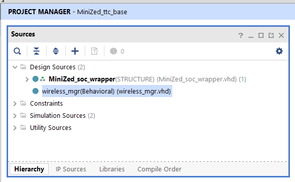
Step 1: Add wireless_mgr.vhd into Vivado project from Project Manager -> Add Sources -> AddFiles

Step 2: Select the VHDL source code. Please don't copy the source into Vivado project.

Project Manager add wireless_mgr.vhd into Vivado project, which is able to be loaded by Vivado Add Module pop-up window at Step 3.
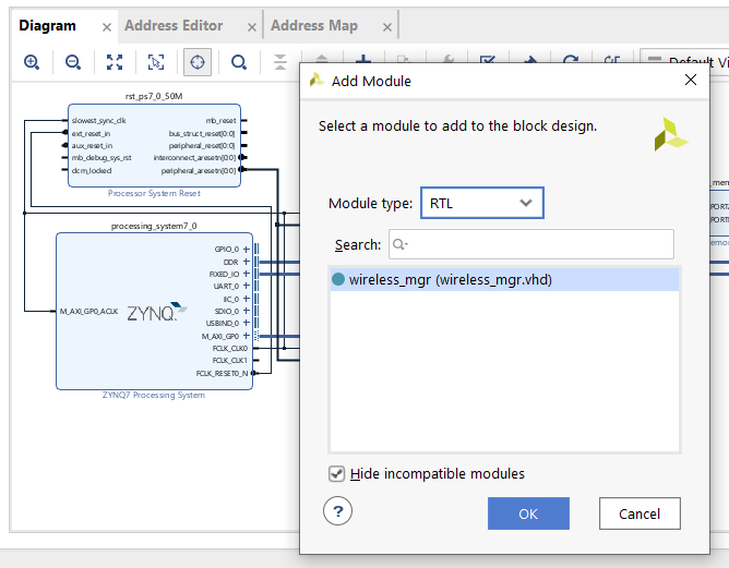
Step 3: Back to Diagram (BD canvas), click the right mouse button under Diagram area. A pop-up window will let us Add Module

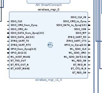
Step 4: After finish click OK at step 3, Vivado will automatically add wireless_mgr_v1_0 block into Diagram.
3. Add Vivado glue logic and reconfig Zynq block as needed. Last, assign Address at Address Editor. Here is the final Lab 9 build from scratch.

Is this same as the original Lab 9 HW design from Avnet?
The answer is no. Why? I forgot to remove jtag to AXI Master module. After synthesis done, Vivado gave me a report about Utilization as below.

MiniZed only has 14400 Slice LUTs totally, my initial reproduced Lab 9 HW design used 17,633 LUTs. Avnet team already figured it out, so Lab 9 training project does not include jtag to AXI Master module due to the limitation of FGPA resource. Here is the final reproduced Lab 9 HW Utilization report and FPGA placement graph.


Conclusions
I learned how to add a user VHDL source into Vivado Diagram and analysis FPGA utilization. There are a lot of features at Vivado ML tool chain, such as FPGA function simulation, more advance TCL scripting for non-project flow, timing analysis, HLS flow and more. I will learn them step-by-step.
References