


Introduction:
The Ultra96-V2 comes with a lot of good pre-built, out-of-box demo material from Avnet to get started quickly. However, the real power of FPGAs is in being able to build custom hardware. In the case of Zynq Ultrascale, which this board is based on, the custom hardware can run along with "hard" A53 and R5 processor cores.
In this blog post, I want to start from the very basics, with the hope that in the subsequent posts we can build upon this to go further. We will basically learn to walk, before we start running. The hope is that anyone starting for the first time with Ultra96 or similar Zynq ultrascale hardware can follow along to get started. This will also help us familiarize ourselves with the tool (Vivado) as well as the basic wokflow used.
In this post I will build the most basic hardware platform, the bare minimum that we need to get the system running and start performing basic talks.
Hardware:
We will be using the following hardware:
- Ultra96-v2-G
- Power Supply (96Boards 4A)
- Ultra96 USB-to-JTAG/UART Pod
- Host machine for development purpose
Software:
For the FPGA "hardware" configuration, the de-facto software from AMD is Vivado. I am using Vivado 2022.2, however the instructions should work with other versions just fine. In my case Vivado (&Vitis) are installed on my windows machine, although the process will stay the same even if you're using Linux (whether directly installed on machine or inside virtual machine).
Project Creation:
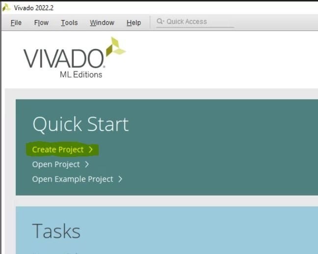
We start by launching Vivado.
Once launched we can click "Create Project" to start the new project wizard.
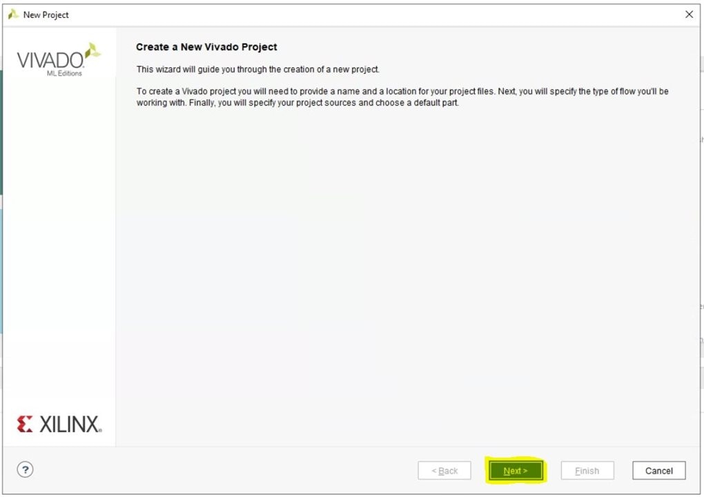
Click "Next" on the first page of the wizard.
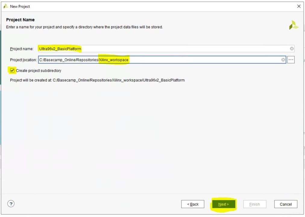
Set the project name, choose appropriate location and make sure the "Create project subdirectory" checkbox is checked so that our projects stay contained within their own folders.
Then click "Next".
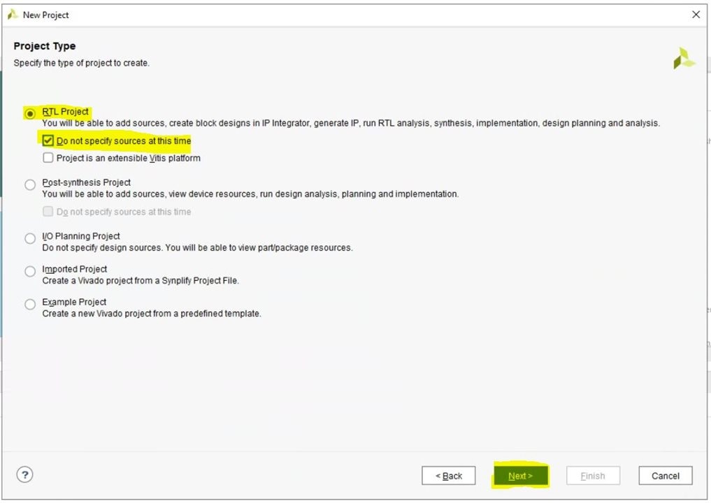
This is going to be a RTL project, and since it's a new design from scratch, select "Do not specify sources at this time" to skip those steps.
Then click "Next".
Since we are working with a board (as opposed to a FPGA part), first we click "Boards" and then click "Refresh" to update the catalog.
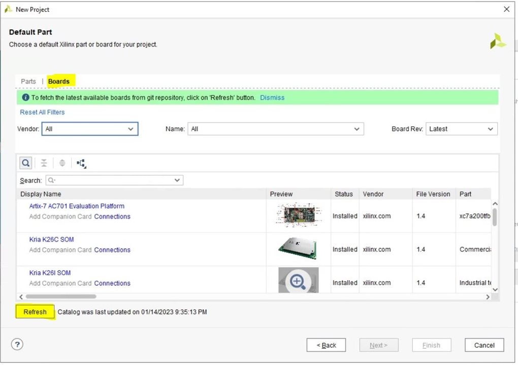
Once the catalog is refreshed, we select "avnet.com" as vendor and then find the "Ultra96-V2 Single Board Computer" from the list.
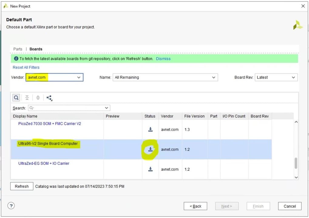
You will notice that this does not enable the "Next" button. This is because this board's data is not yet downloaded to our Vivado installation.
Click the download button in front of this board to download the data for this board. The process will only take a few seconds. Once finished, you will see more information getting populate about the board in the columns in front. And the "Next" button is not greyed out anymore, so we click it to proceed.
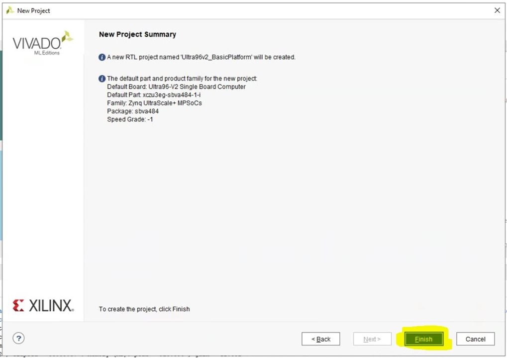
At this point we can review the summary and click "Finish" since all looks good.
After a minute or so Vivado is finished with creating the new project and we reach the main Window
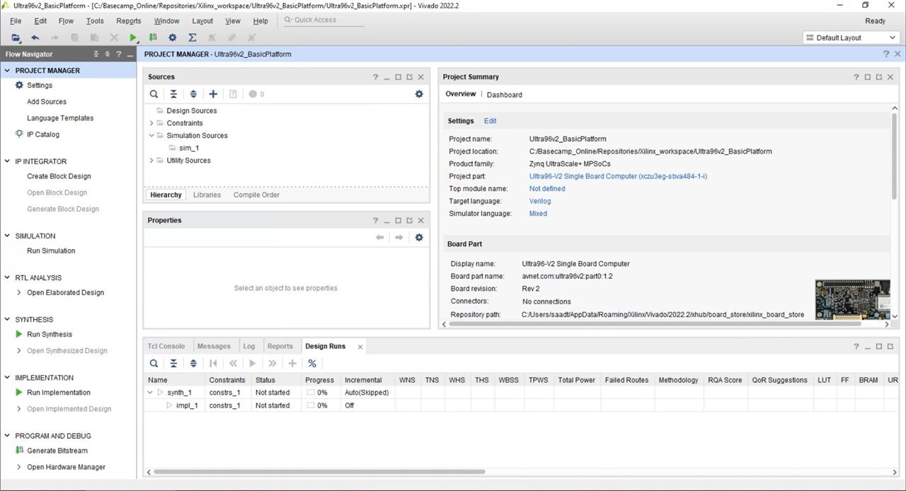
This concludes the process of creating the project.
Creating the Ultra96v2 Block Design:
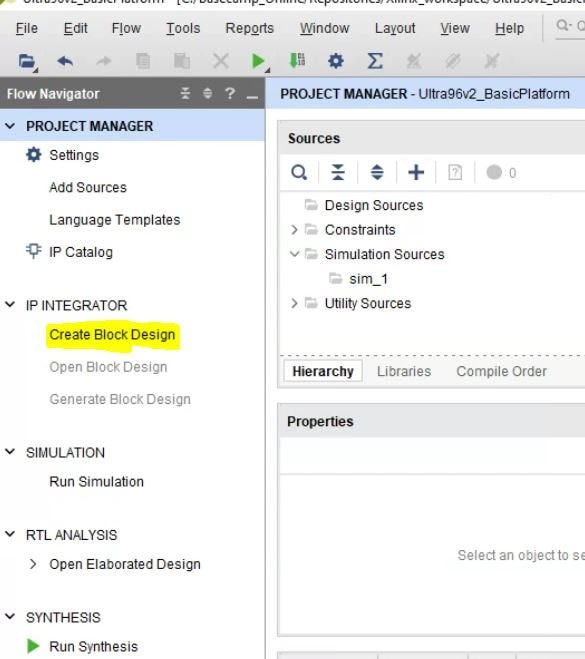
To start creating the block design, click "Create Block Design" form the Flow Navigator window.
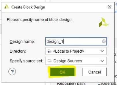
In the window that appears, we can leave things to default, although you could give a different name to the block design. Especially later if you are going to create multiple different block designs, then it's better to name them appropriately. Click OK to proceed with creating.
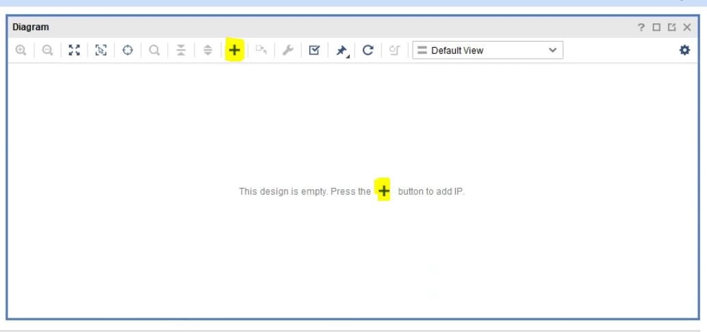
A progress window will appear, and take several tens of seconds. Once it's done, it will disappear and the empty block design is shown.
To start adding IPs our designs, we click either of the "Add IP" buttons:
This will bring forth the list of IPs that we can add. We are interested in the "Zynq Ultrascale+ MPSoC" which is the IP that represents the "hard" Zynq processing system on this board's ZU3EG FPGA. To make it easier to find it, we can type "zynq" in the filter text box and then double click the "Zynq Ultrascale+ MPSoC" IP.
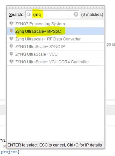
Note that some other Zynq IPs are also there, but they are not relevant to the part on this board's FPGA so they are greyed out.
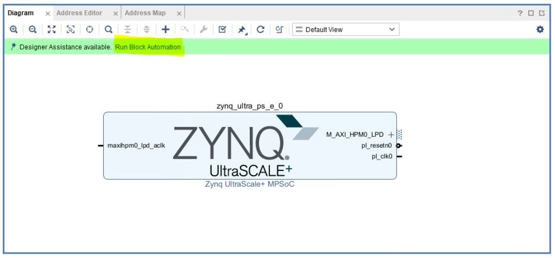
Double-clicking the IP will add it to our system. The block at this point is unconfigured and not connected. To make things work properly, a lot of things need to be configured correctly. Luckily, Vivado makes it very easy for standard boards because it already downloaded the presets for the Ultra96-v2 board. All we need to do is click "Run Block Automation" to execute this automated process.
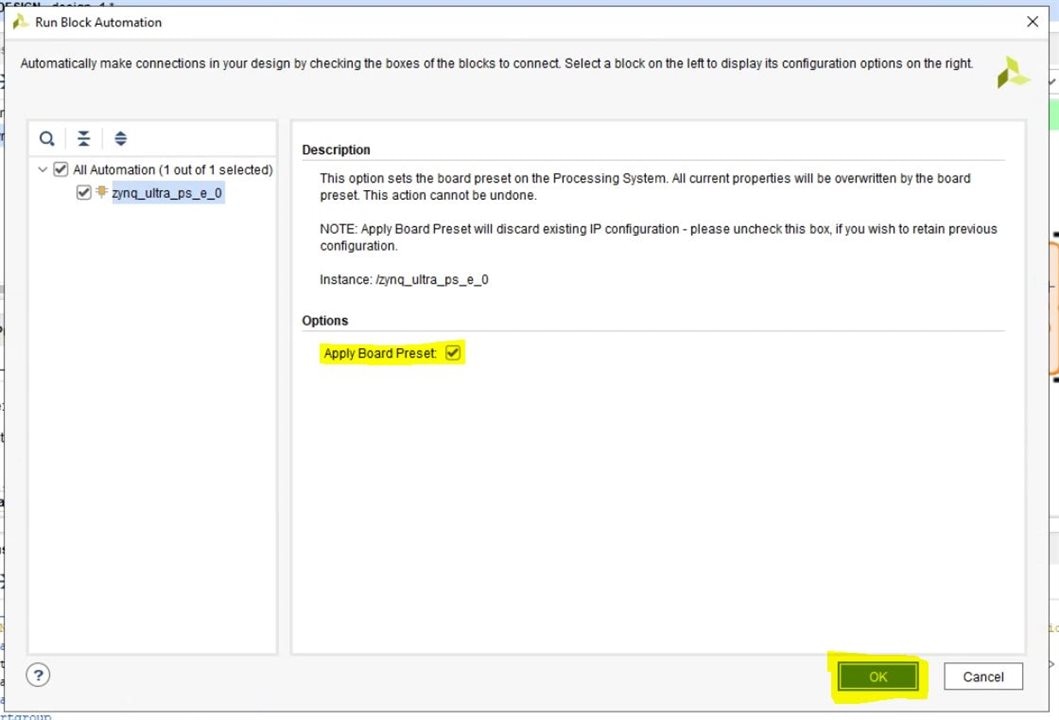
This brings up the "Run Block Automation" window. Make sure the "Apply Board Preset" checkbox is selected (by default) and click OK.
The process only takes few seconds, and once done, you will notice some changes on the Zynq block. This is because of the board presets applied by the automation process.
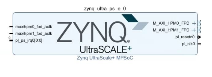
The two clock ports on the left side maxihpm0_fpd_aclk and maxihpm1_fpd_aclk must have a clock connected to them. To do this, we can connect them to pl_clk0 clock output from the Zynq block. To make the connection, click and drag the mouse from the pl_clk0 port's pin to the other two ports' pins.
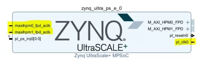
This will make the necessary connections and we obtain the following diagram:
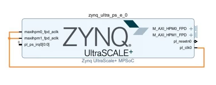
Since we are going for the most basic hardware platform, we will not make any other connections for now.
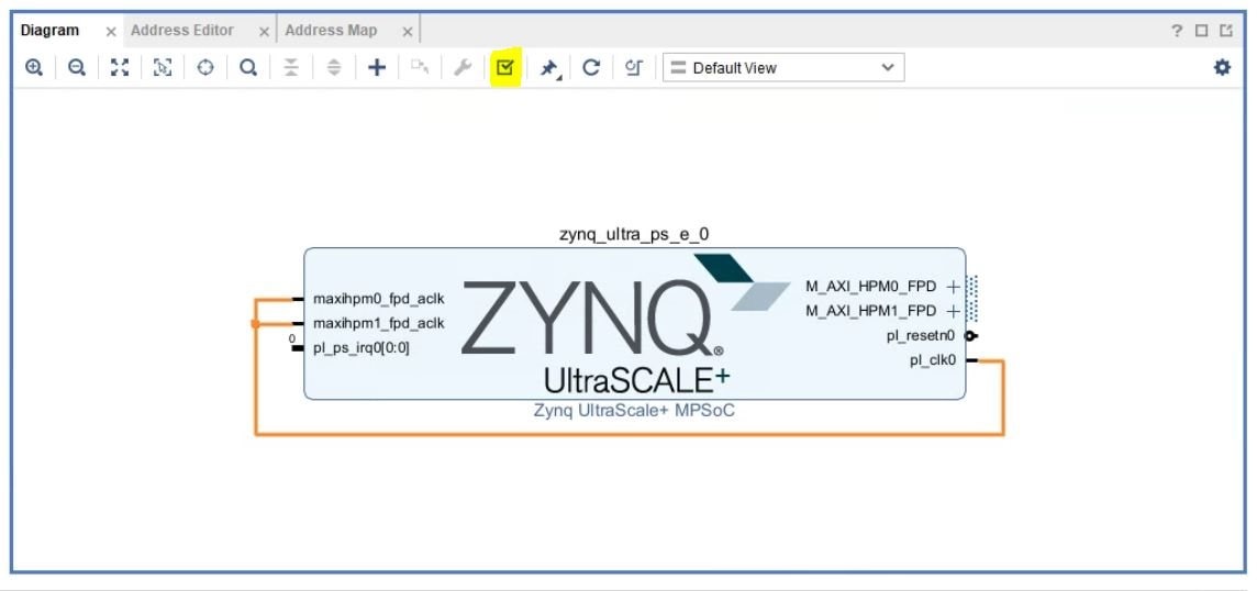
To validate the design (check for errors), we click the "Validate Design" icon.
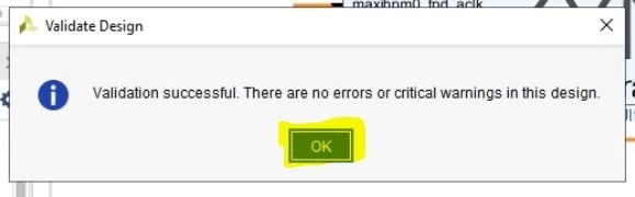
If the validation is successful, we receive the following message. Click OK to dismiss it.
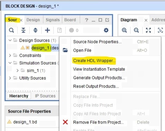
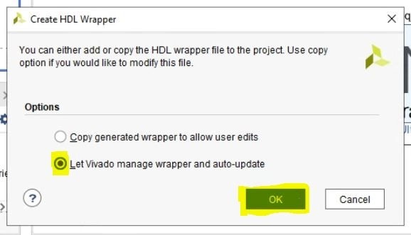
Now we need to create a HDL wrapper for our block design. In the Block Design window, first click "Sources" tab. Then, find the "design_1" element, right-click it and select "Create HDL Wrapper"
A window will appear if we want to manage the wrapper. We let Vivado manage it instead. Click OK to proceed.
This process can take few tens of seconds.
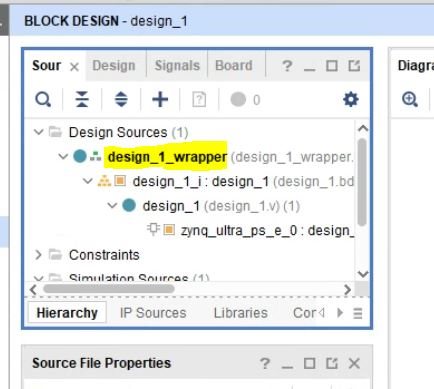
You will notice that in the Sources hierarchy our original design is shown under the new "design_1_wrapper".
At this point we can save our project.
Generate bitstream and Export platform for Vitis
Now all that is left is to Synthesize the design, Implement it and generate bitstream. Actually we can just command Vivado to generate the bitstream and it will do the synthesis and implementation already (since they are required before generating the bitstream). Click the "Generate bitstream" in the Flow Navigator under "Program and Debug"
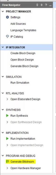
This will start the process of Synthesis -> Followed by Implementation -> Followed by Bitstream Generation.
This can take anywhere between few minutes to several hours depending on the design complexity and the host machine's computing power. Since ours is a relatively basic design, this should only take few minutes.
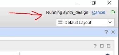
You can monitor the progress by looking at the status in the top-right of screen
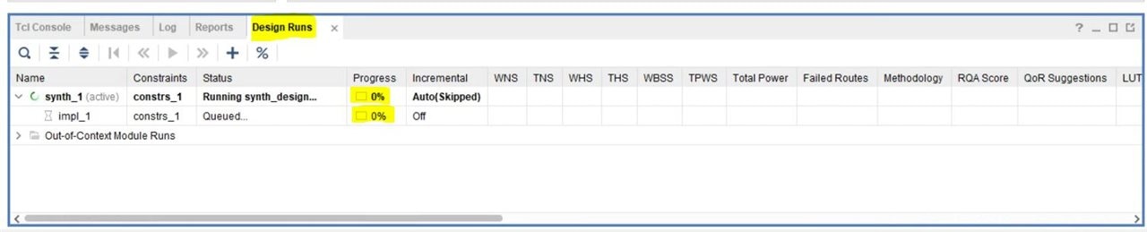
Another place to monitor this progress is in the "Design Runs" window at the bottom of the screen which shows the progress in more detail
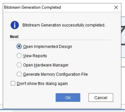
Once the process completes successfully, we will be presented with the following window. Press OK to open the implemented design.
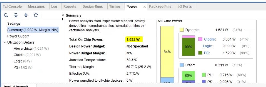
Once the implemented design opens, we can look at various reports. For example, under the power report, We can see that our bare minimum design will consume about 1.9 Watts of power. Remember that this is an estimated power based on some assumptions since Vivado doesn't know 100% of your design and it's usage while running. Nevertheless it gives a good ball-park figure.
Now all that's left is the export our hardware platform for Vitis.
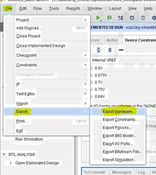
To do this, Click File -> Export -> Export Hardware.
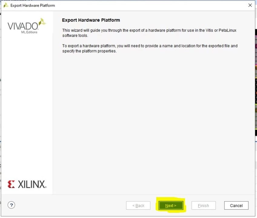
This opens the Export Hardware Platform wizard. Click Next on the first page.
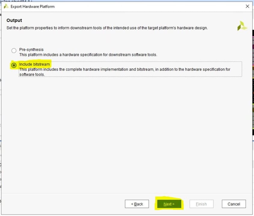
Make sure "Include bitstream" is selected. The pre-synthesis option is if you want your software team to start working even before the hardware design is compiled.
Click Next.
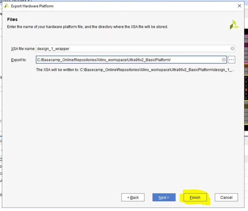
On the last page, you can change the name of exported hardware platform file, as well as change the export location if needed. In my case I proceed with defaults and click Finish.
The process will run for a few seconds and then disappear, meaning the hardware platform file has been exported.
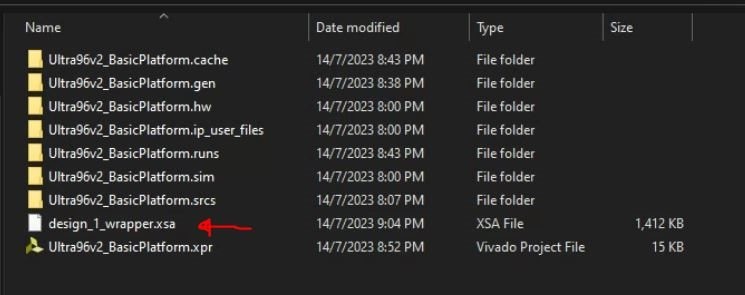
Now, if we go into the folder where we eported the file, we will see the exported .xsa file
This completes our tutorial for creating a basic hardware platform for the Ultra96-V2 in Vivado 2022.2.
In future blogs, we will use this exported platform to run some software applications on our processor(s).
Thanks for reading and following along! See you next time!
Top Comments
-

navadeepganeshu
-
Cancel
-
Vote Up
0
Vote Down
-
-
Sign in to reply
-
More
-
Cancel
Comment-

navadeepganeshu
-
Cancel
-
Vote Up
0
Vote Down
-
-
Sign in to reply
-
More
-
Cancel
Children