Table of Contents
Introduction
Coming to the last training blog, its amazing to realize how vast the technology is - packed inside one Zynq SoC and glad to have some of it explored and understood building solutions around it and this training series greately helped me in walking the unwalked pathway. Throughout this blog, I am exploring the end-to-end design flow and implementing I2C, SPI serial interfaces through the onboard Pmod and Arduino ports.
The Design Flow Simplified
Starting off, lets be clear how much is the pathway. Apparently, we need not use/configure all the features and options available in a standard AMD-XILINX FPGA flow and need to be conservative about the project's processing power demand and time used to build it. Here, the overall flow involves:
- Creating a new Vivado project
- Creating a block desing with Zynq
- Adding peripheral IPs(Pmod_NAV, axi_gpio, axi_quad_spi, axi_iic)
- Running the synthesis process
- Preparing a constraints file(with Minized board constraints file reference) to map the IP block I/Os to the FPGA I/O pins.
- Generating bitstream(.bit) file directly
- Exporting the vivado platform file(.xpr) to the Vitis software developemnt platform
- Importing the platform in Vitis and creating a new application project on top of this platform
- Wriiting application code and running the system
Adding interfaces (Pmod NAV, TFT LCD, HTU21D)
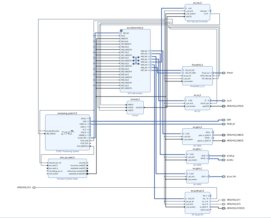
After creating the new project in Vivado, here comes the first step. I have a couple of sensors to be interfaced and a 1.8 inch TFT display. Thinking about the blocks required, we need the Zynq PS(the whole processing system block), AXI Interconnect(to link PS to PL) and multile interface blocks like Pmod_NAV, axi_gpio, axi_quad_spi, axi_iic for LEDs, Pmod, I2C sensor and SPI based TFT display. For I2C, SPI, UART etc., we have an option to use either the PS existing serial interfaces or use the axi_'x' IP blocks on the PL.
The unavailabe IPs can always be added through the import process as shown Using Digilent Pmod IPs in Vivado and Vitis (Under Construction) - Digilent Reference. Here's the full block design(.bd):

The Vivado tool helps in autorouting the IPs and rearranging the bocks tidyly. Moving on, next comes the activity of setting up the constraints file.
Project Constraints File
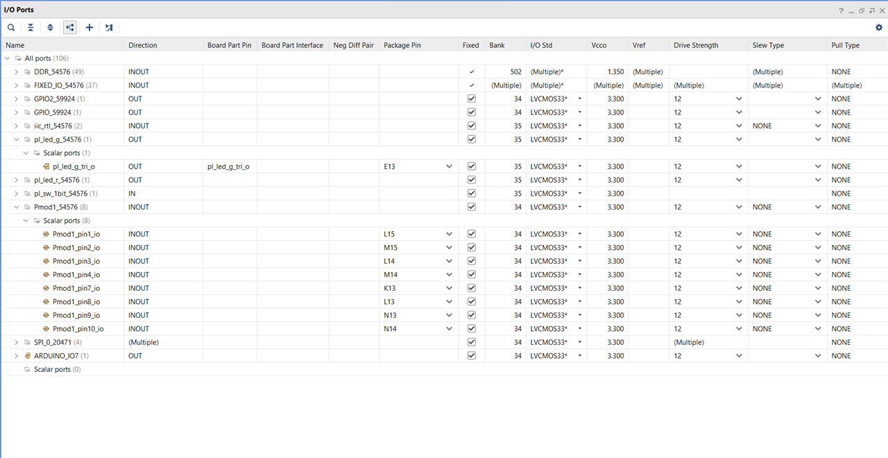
This seems a bit confusing, but nothing is to be created from scratch. Based on the board selected during the project creation and the IPs added, as soon as you open the synthesized desing and going to the I//O ports, a tabular window shows up where all the ports are shown, assigned directions and we need to then select the right I/O standard(example: LVCMOS33) and the package pin.

With respect to the chosen board, the peripheral mappins can be seen and used to choose the pins. The MiniZed pin constraint file is given here hdl/Boards/MINIZED/minized_pins.xdc at master · Avnet/hdl (github.com) and this is what I had to customized and entered for project specific configuration(.xdc):
set_property IOSTANDARD LVCMOS33 [get_ports {ARDUINO_IO9[0]}]
set_property IOSTANDARD LVCMOS33 [get_ports {ARDUINO_IO8[0]}]
set_property IOSTANDARD LVCMOS33 [get_ports iic_rtl_scl_io]
set_property IOSTANDARD LVCMOS33 [get_ports iic_rtl_sda_io]
set_property IOSTANDARD LVCMOS33 [get_ports Pmod1_pin1_io]
set_property IOSTANDARD LVCMOS33 [get_ports Pmod1_pin2_io]
set_property IOSTANDARD LVCMOS33 [get_ports Pmod1_pin3_io]
set_property IOSTANDARD LVCMOS33 [get_ports Pmod1_pin4_io]
set_property IOSTANDARD LVCMOS33 [get_ports Pmod1_pin7_io]
set_property IOSTANDARD LVCMOS33 [get_ports Pmod1_pin8_io]
set_property IOSTANDARD LVCMOS33 [get_ports Pmod1_pin9_io]
set_property IOSTANDARD LVCMOS33 [get_ports Pmod1_pin10_io]
set_property IOSTANDARD LVCMOS33 [get_ports {ARDUINO_IO10[0]}]
set_property IOSTANDARD LVCMOS33 [get_ports ARDUINO_IO11]
set_property IOSTANDARD LVCMOS33 [get_ports ARDUINO_IO12]
set_property IOSTANDARD LVCMOS33 [get_ports ARDUINO_IO13]
set_property IOSTANDARD LVCMOS33 [get_ports {ARDUINO_IO7[0]}]
set_property PACKAGE_PIN L15 [get_ports Pmod1_pin1_io]
set_property PACKAGE_PIN M15 [get_ports Pmod1_pin2_io]
set_property PACKAGE_PIN L14 [get_ports Pmod1_pin3_io]
set_property PACKAGE_PIN M14 [get_ports Pmod1_pin4_io]
set_property PACKAGE_PIN K13 [get_ports Pmod1_pin7_io]
set_property PACKAGE_PIN L13 [get_ports Pmod1_pin8_io]
set_property PACKAGE_PIN N13 [get_ports Pmod1_pin9_io]
set_property PACKAGE_PIN N14 [get_ports Pmod1_pin10_io]
set_property PACKAGE_PIN M10 [get_ports {ARDUINO_IO10[0]}]
set_property PACKAGE_PIN M11 [get_ports ARDUINO_IO11]
set_property PACKAGE_PIN R11 [get_ports ARDUINO_IO12]
set_property PACKAGE_PIN P11 [get_ports ARDUINO_IO13]
set_property PACKAGE_PIN N8 [get_ports {ARDUINO_IO7[0]}]
set_property PACKAGE_PIN G15 [get_ports iic_rtl_scl_io]
set_property PACKAGE_PIN F15 [get_ports iic_rtl_sda_io]
set_property PACKAGE_PIN M9 [get_ports {ARDUINO_IO8[0]}]
set_property PACKAGE_PIN N9 [get_ports {ARDUINO_IO9[0]}]
After this, generating the bitstream right away and exporting the hardware! Let's see you again on the other side of the planet....
Software Implementation
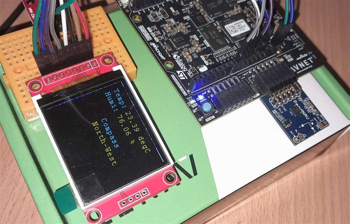
Now that we have come to the software side, its all about getting the application code right. The PL implemented peripherals are already memory mapped and only have to be called and referenced back as a part of this activity to give life to the system by reading sensors and seeing some colour on the TFT display. Here, the HTU21D and TFT LCD ibraries are used which includes fonts and styles for the display. I will post the full project file on this GitHub repo soon NavadeepGaneshU/Path-to-Programmable-III_MiniZed: Project files with blog links of exploration with MiniZed board on path to programmable element14 community contest (github.com)
/*
 * Program for multi-sensor interface and display on 1.8 inch TFT with MiniZed
 * using the PL defined Pmod, GPIO and SPI IP blocks
 * More details and full source file at https://github.com/NavadeepGaneshU/Path-to-Programmable-III_MiniZed
 *
 * TFT 	| MiniZed
 * --------------
 * Vcc 	| 5V
 * GND 	| GND
 * CS  	| IO_10
 * RESET| IO_8
 * A0	| IO_9
 * SDA	| IO_11
 * SCK	| IO_13
 * LED	| 3.3V
 *
 * HTU21D pin maps to SDA and SCL of the MiniZed arduino header pins
 * Pmod NAV at Pmod 1
 *
 */

/***************** Includes *****************/
#include <stdio.h>
#include <sleep.h>
#include <time.h>
#include "platform.h"
#include "xil_printf.h"
#include "xparameters.h"
#include "xgpio.h"
#include "xstatus.h"
#include "delay/Delay.h"
#include "SPI.h"
#include "htu21d.h"
#include "lcd/LCD_Driver.h"
#include "lcd/LCD_GUI.h"
#include "htu21d.h"

/***************** User Definitions *****************/
#define BACKGROUND  WHITE
#define FOREGROUND BLUE
#define DELAY 1000

/***************** User Peripheral Instances *****************/
extern XGpio gpio1;
extern XSpi  SpiInstance;
extern const unsigned char font[] ;

void htu21d_main_menu(void);

int main()
{
    int Status;
	float temperature;
	float relative_humidity;

	htu21d_status stat;

	char tempbuf[16] = {};
	char humibuf[16] = {};

    init_platform();	    //Initialize the UART

	/* Initialize the GPIO driver */
	Status = XGpio_Initialize(&gpio1, XPAR_AXI_GPIO_0_DEVICE_ID);
	if (Status != XST_SUCCESS) {
		xil_printf("GPIO Initialization Failed!\r\n");
		return XST_FAILURE;
	}

	/* Set up the AXI SPI Controller */
	Status = XSpi_Init(&SpiInstance,SPI_DEVICE_ID);
	if (Status != XST_SUCCESS) {
		xil_printf("SPI Initialization Failed!\r\n");
		return XST_FAILURE;
	}

    /* Set the AXI address of the IIC core */
    htu21d_init(XPAR_AXI_IIC_0_BASEADDR);

    /* TFT LCD initialization */
    LCD_SCAN_DIR LCD_ScanDir = SCAN_DIR_DFT;	//SCAN_DIR_DFT = D2U_L2R
	LCD_Init(LCD_ScanDir );

	stat = htu21d_set_resolution(htu21d_resolution_t_14b_rh_12b);		// Set resolution to 12-bit RH and 14-bit Temp

    while(1)
    {
		 stat = htu21d_read_temperature_and_relative_humidity(&temperature, &relative_humidity);
		 if(stat==htu21d_status_ok){
			 //printf("Temperature : %5.2f%cC, \tRelative Humidity : %4.1f%%",temperature,248,relative_humidity);
		 }else if(stat==htu21d_status_i2c_transfer_error){
			 printf("Transfer Error.");
		 }else if(stat==htu21d_status_crc_error){
			printf("CRC Error.");
		 }

		LCD_Clear(GUI_BACKGROUND);

		NavDemo_Initialize();
		NavDemo_Run();
	    NavDemo_Cleanup();

		GUI_DisString_EN(10,10,"Temp:",&Font12,GUI_BACKGROUND,CYAN);
		GUI_DisString_EN(10,25,"Humi:",&Font12,GUI_BACKGROUND,CYAN);

		sprintf(tempbuf, "%2.2f degC ", temperature);
		sprintf(humibuf, "%2.2f %%", relative_humidity);

		GUI_DisString_EN(55,10,tempbuf,&Font12,GUI_BACKGROUND,YELLOW);
		GUI_DisString_EN(55,25,humibuf,&Font12,GUI_BACKGROUND,YELLOW);

    }
    return 0;
}

/* External file: TFT printing snippet from pmod_nav.c*/

/* print this on the TFT display */
GUI_DisString_EN(50,50,"Compass",&Font12,GUI_BACKGROUND,CYAN);
sprintf(compassbuf, "%s", str);
GUI_DisString_EN(50,65,compassbuf,&Font12,GUI_BACKGROUND,YELLOW);

/* End of External file: TFT printing snippet from pmod_nav.c*/
Demo Video


