Table of Contents
Introduction
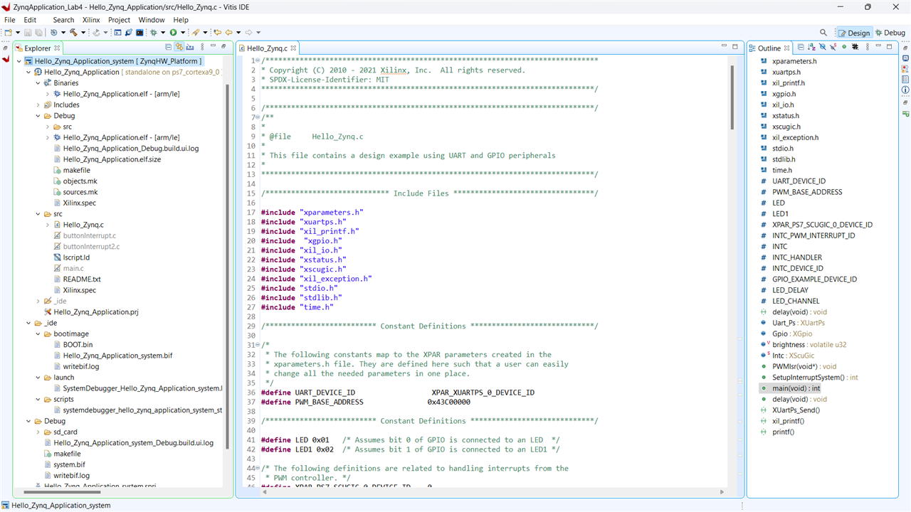
Path to Programmable III is an interesting contest and with the MiniZed board, I started off with the software track. This training contains everything about using the existing platform .xsa file and building applications over Vitis tool over this platform. Through this, I got to learn about the method to build software applications on the ZYNQ PS, working of the flash and booting, first stage bootloader and then using AMD-Xilinx libraries in the software application.
In this module, I will explain how I got started with building a basic application and ended up making a no-sense app that just keeps doing the random number generation and lights up the LED.
What's all this platform?
This starts with creating an application project as there is already a platform available exported from Vivado in this case. So generally, in this implementation flow above the hardware, the platform project comes in, and then the application project. I am using the ZynqHW_Platform here directly without any modifications.

At this point, I was curious to know the hardware block design of this platform to see what blocks exist in connection to Zynq. Although I found there is a way to do it as it is told that design_1_bd.tcl file is existent in the .xsa extract, this platform did not thave this file (Reverse engineering the xsa file · Wiki · Projects / SoC Course with Reference Designs · Open Hardware Repository (ohwr.org)). If existed, I presume it could be opened from the vivado tcl console by source design_1_bd.tcl. Anyways, after jumping to the hardware section of the lab and opening the design vivado project file, I was able to see the design.
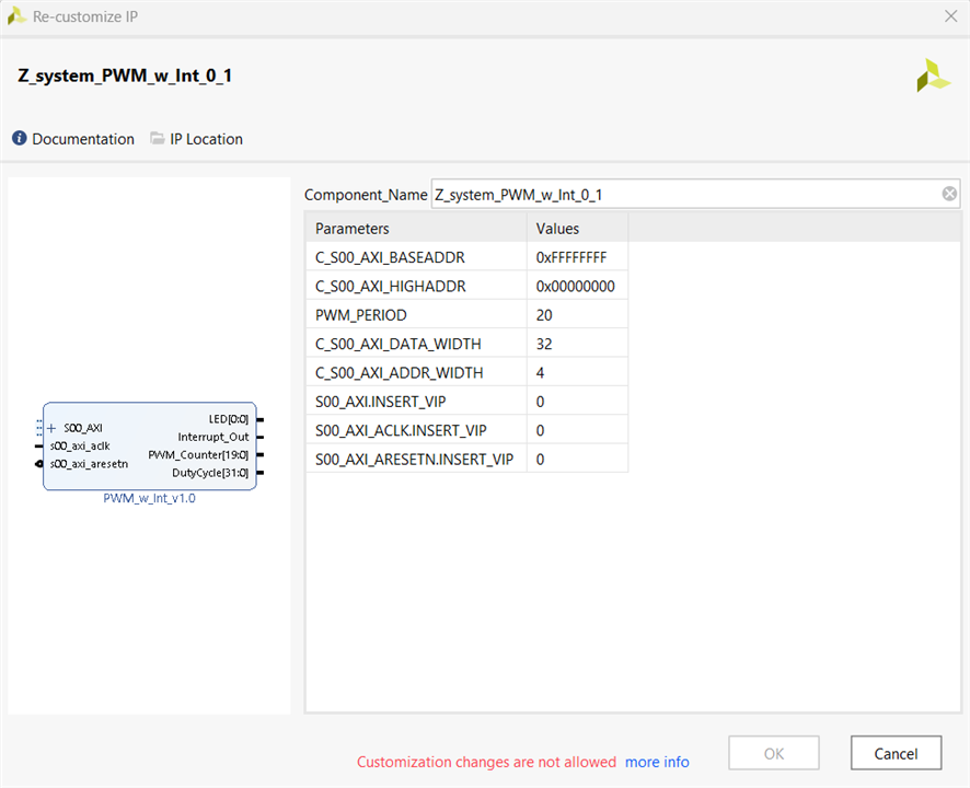
Concerning the software side, it is interesting to see how the custom PWM_w_Int IP drivers and ps7_cortexa9 set with a board support package and bootloader are integrated into the platform. The first stage bootloader plays a role to:
- Initialize Processing System blocks including
- Phase lock loop (PLL) to adjust the driving frequency for peripherals
- External memory controller
- Multiplexed input/output (MIO)
- Configure Programmable Logic with Bitstream
- Provide for secure boot option
- Execute application code
So this simplifies the task of using the processor system (PS) and makes it as close as to a microcontroller with all peripherals integrated and selectable.

The application project then created sits on top of this and includes general C programming development flow on the cortex a9 target.

Using printf(), xil_printf(), XUartPs_Send()
One thing that I encountered is the existence of library to print the data to the serial console directly using the UART. In a cross-complied environment, usually, it involves the use UART library and via the machine COM port, the serial data is read. Classically, the stdio.h header file includes printf() and if that is defined and printf is called in the application code, even though there is no instance of the function and ability to print, the program builds successfully with a small warning saying 'implicit declaration of function printf()' which obviously makes sense because of dynamic linking.
The xil_printf() is the function here that directly takes the string as an argument and passes it on to print serially through UART. Wondering about this and looking at the call hierarchy, it is a derivative from XUartPs_SendByte() function that is part of the xuartps_hw.c in the BSP. So all this play was done just for the matter of simplification to the user.

Or it can still be done so for classical programmers,...haha
#define printf xil_printf /* Smaller footprint printf */
Using the PWM module
PWM_w_Int is a custom, locked IP provided as a part of this board package. Looking into the block design, the output goes to LED[0:0] which is the onboard RED LED. Additionally, this and the counter outputs are connected to the integrated logic analyzer (ILA) which is a customizable IP integrated into the system.


Looking into the ILA window in vivado, the counter can be seen incrementing and the LED PWM signals ON and OFF.
| {gallery}ILA View |
|---|
|
|
|
|
|
|
 |
The application
This uses GPIO and UART libraries and a random number generator to decide the brightness of the onboard LED. The test sequence is printed over UART.
/*Generating a random number with user-defined upper and lower bound*/

int lower = 9;
int upper = 0;

int num = (rand() % (upper - lower + 1)) + lower;
/*Send a hello message and activity status*/
xil_printf("Hello from MiniZed!\r\n");
xil_printf("Activity 1: Picking a random LED colour.\r\n");

led_id = (rand() % 3);

led_str = (led_id == 0)?("RED"):(led_id == 1)?("GREEN"):("AMBER");

xil_printf("LED colour %d picked\n\r", led_id);

/* Set the LED to High */
if(0 == led_id)
	XGpio_DiscreteWrite(&Gpio, LED_CHANNEL, LED);
else if(1 == led_id)
	XGpio_DiscreteWrite(&Gpio, LED_CHANNEL, LED1);
else if(2 == led_id)
{
	XGpio_DiscreteWrite(&Gpio, LED_CHANNEL, LED);
	XGpio_DiscreteWrite(&Gpio, LED_CHANNEL, LED1);
}

delay();

/* Clear the LED bit */
XGpio_DiscreteClear(&Gpio, LED_CHANNEL, LED);
XGpio_DiscreteClear(&Gpio, LED_CHANNEL, LED1);
delay();
xil_printf("\n\n");		/*goto new line*/

xil_printf("Activity 2: Changing LED brightness randomly.\r\n");
print("Random number generator running....\n\r");

for(count = 0; count < 10; count++)
{
	delay();
	/* Read an input value from the random number generator. */
	period = rand() % 10;

	/* Print the input value back to the console to provide some
	 * feedback to the user. */
	xil_printf("Brightness Level %d picked\n\r", period);

	/* Since the LED width is 1e6 clk cycles, we need to normalize
	 * the period to that clk.  Since we accept values 0-9, that will
	 * scale period from 0-999,000.  0 turns off LEDs, 999,000 is full
	 * brightness. */
	brightness = period * 110000;

	/* Write the duty_cycle width (Period) out to the PL PWM
	 * peripheral. */
	Xil_Out32(PWM_BASE_ADDRESS, brightness);
	xil_printf("\n\n");		/*goto new line*/
}
This video shows the random number generator running in loop for 10 iterations and controlling the brightness of PL RED LED. There are two activities:
1. Pick a random colour from RED, GREEN and AMBER
2. Pick a random number between 0 to 9 for 11 iterations and control the RED LED brightness accordingly.

Thanks for reading through. In the upcoming blog, I'll write about my exploration with hardware/software interrupts, interacting I2C display and then using the onboard IMU to build a sensor fusion project.
Tutorial queries
1. Is it possible to view the vivado block design from the exported .xsa platform file?
2. Is there a way to analyze core utilization(FLASH, RAM, CPU usage %) for the deployed application in vitis?
3. Does vivado performance get optimized by having a GPU and in the process of synthesis and bitstream generation is GPU utilized?


