Microphone and Speaker Modules
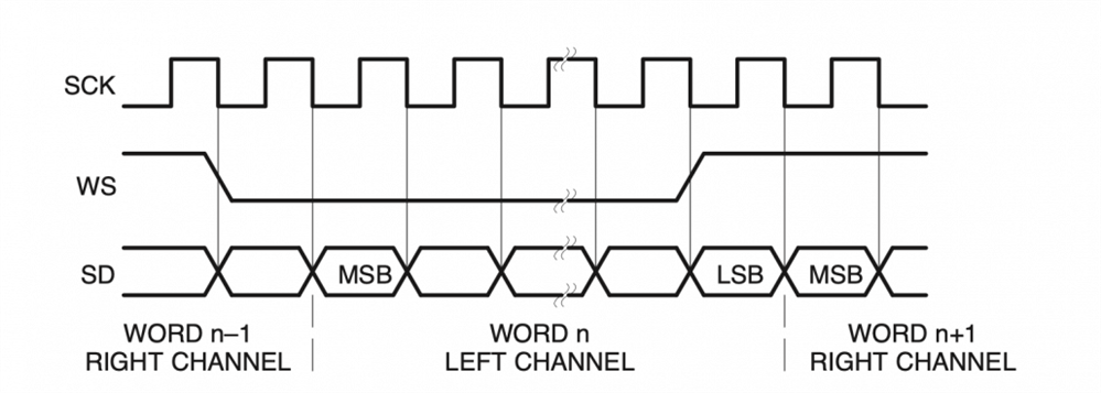
Our microphone and audio decoder use the i2s protocol, a protocol for sending and receiving audio. Below is the i2s timing diagram.

Figure: i2s timing diagram
Basically the code should set the ws, then send a bit of data, and then trigger the clock. One issue with PIO is that it mainly operates with one output pin, which is best used for data. This is solved using side_set, a feature of PIO to set up to five pins per PIO program per instruction.
Timing is important since the sample rate determines how many times to collect/send data. For standard cd audio, it is 44100 Hz. Using 32 in the sample period (1/sample_frequency) means the frequency must be 32/(1/sample_frequency). That means the frequency must be 1.4112 MHz. The pico C-Sdk allows us to set the clock rate of only the PIO portion of code, which divides the system clock of 125MHz. The clock divider is 125MHz/1.4112MHz which is calculated in code.
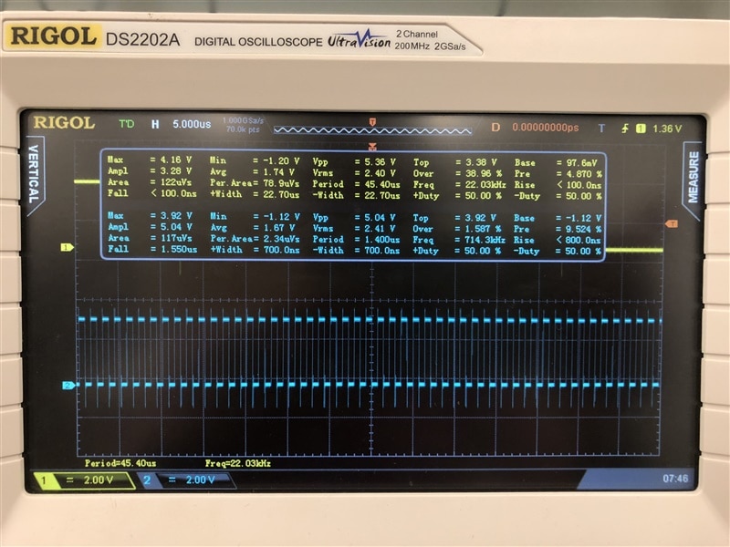
To test, we used a middle C note (around 261 Hz) in the form of a square wave. The data is 16 bit signed per channel, so the max value is +- 32767 and is used to make sure the sound will be heard if it works. When we tested, it didn’t work at all, we only heard weird noises coming from both channels. The first problem we had was how C treats negative values. Since both channels are sent together in the PIO, the negative values must be combined in such a way that one channel in the higher 16 bits and the other in the lower 16 bits. The solution was to OR both channels and mask out the ones brought in by shifting: (-(RIGHT << 16) & 0xFFFF0000) | -LEFT. Next issue was the pin configuration. We initially confused SCK with WS, which we resolved with the help of an oscilloscope showing the frequencies. As can be seen below, channel 1 (WS) has a frequency of 22 KHz and channel 2 (SCK) has a frequency of 714 KHz.

Figure: Comparing WS and SCK signals
Although the mic uses i2s, the formatting was different enough to require additional changes other than flipping the direction of the data lines to input. The mic didn’t work correctly until we used 32 bits for each channel,l configured the pins as input, and truncated the 32 bit input to 16 bits per channel. After these problems were solved, we had a working mic and speaker!
Wifi Module
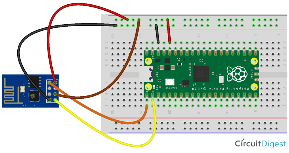
To add wifi functionality to the pico we chose the esp-01 module, partly because a makerpi board had a slot for it and partly because it could be programmed with Rust, a language we eventually didn’t use. This turned out not to be a big deal since we discovered how to use the AT commands preinstalled on the firmware.

Figure: Wifi module wiring
AT commands work by sending strings from the pico to esp over UART. The strings configure and send data in a language agnostic way. The basic flow is to send a command and then look for an “OK” or “ERROR” response. Depending on the response we continue with another command or resend the command. The easiest method we found to send data is over TCP. The esp module has a command to create a server and a command to connect to a client.
By trial and error we learned that sending multiple commands at once caused problems since one was already being processed. The data being sent must also have a carriage return character (‘\r’) in addition to a new line (‘\n’) to be processed correctly. The TCP server can’t have a connection to a client when restarting the whole pico program. Sending and receiving UART information must be carefully done because the UART rx and tx queues might still contain data and won’t work correctly if the code grabs the wrong information. After getting over all the roadblocks we finally managed to send data from one pico to another as can be seen below.
