 Blog#2 Design -- Pi Fest - Music/Audio Project
This blog is part of a blog series for the Pi-Fest Design Challenge.
This blog will include the Design of my Idea.
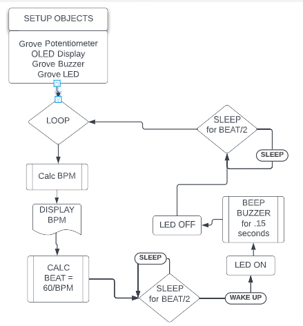
Firmware Design
This section will describe my design of the Firmware that will run on the PICO to implement my metronome Idea.
Hardware Design
This section will describe the circuit design using the Pico and other electronics, to implement my metronome idea.
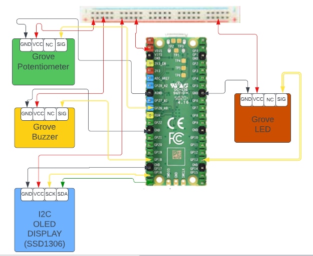
ELECTRONIC Components
-
PICO
- PIN Side view
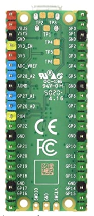
- Top View
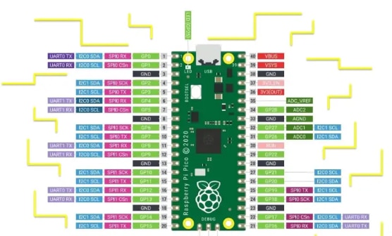
- OLED Display
- Grove Components
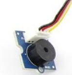
- Buzzer
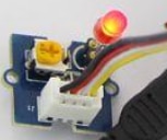
- LED
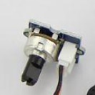
- Potentiometer
- Buzzer
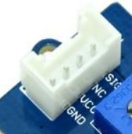
- Grove Connector and Cable described
- Each Grove component has a Grove colored coded cable attached to Grove connector on the Grove Board. I used the end of the cable to attach jumper cables to the be attached to the appropriate pins on the Pico.
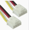
- One end of the cable has a notch so there is no way to make a bad connection
- As described in the connector below The BLACK goes to GND, The RED goes to VCC and the YELLOW goes to SIG on the Groove connector. I use these colors on the other end to connect my jumper wire. The WHITE wire is NOT SED>

References
This section includes some links that I found helpful.

