 Blog#3 Testing- Music/Audio Project
This blog is part of a blog series for the Pi-Fest Design Challenge.
This blog will describe the unit testing I performed on the 4 electronic components that I attached to the PICO. The Wiring diagram and the code for each of the 4 components that I will attach to the PICOis depicted in this blog. I then used the code to implement my design code.
UNIT Testing
-
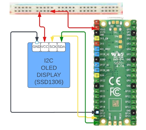
PICO to Display
- This test will display 100 on the SSD1306 OLED screen along with a title.
-
Wiring
-
CODE
from machine import Pin, I2C
import ssd1306

# setup the I2C communication
i2c = I2C(0, sda=Pin(16), scl=Pin(17))
display = ssd1306.SSD1306_I2C(128, 64, i2c)

bpm = 100

# The following part changes according to what you want to display
display.text('Beats Per Minute,', 0, 0)
display.text('----------------', 0, 16)
display.text(str(bpm),50, 32)
display.text('----------------', 0, 48)


# The following line sends what to show to the display
display.show()
-
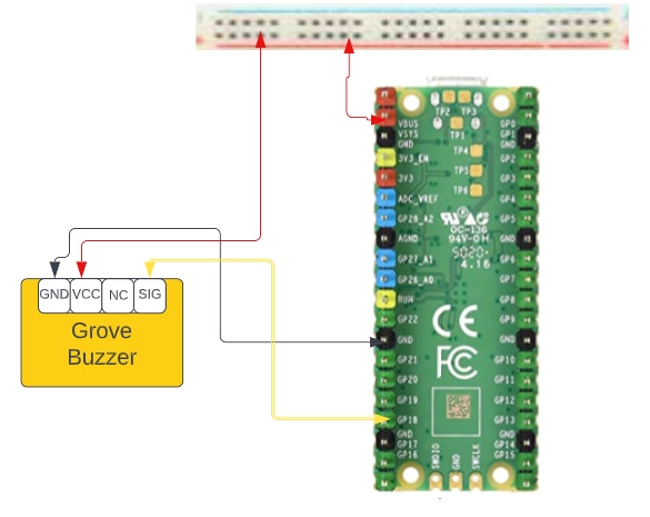
PICO To Buzzer
- This test will turn the Grove buzzer on and off.
-
Wiring
-
CODE
# Active Buzzer that plays a note when powered
from time import sleep
from picozero import Buzzer

buzzer = Buzzer(18)

buzzer.on()
sleep(1)
buzzer.off()
sleep(1)

buzzer.beep()
sleep(4)
buzzer.off()
-
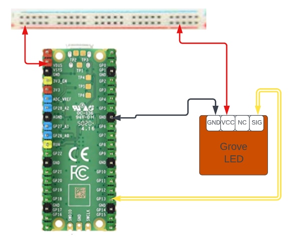
PICO to LED
- This test will blink the Grove LED every half second.
-
Wiring
-
CODE
from machine import Pin
from time import sleep

led = Pin(13, Pin.OUT)

while True:
    led.toggle()
    sleep(0.5)
-
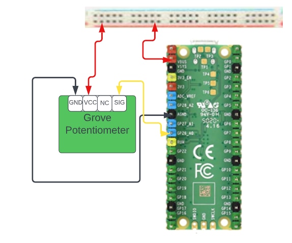
PICO to Potentiometer
- This test will print the Potentiometer value on the PC serial port.
-
Wiring
-
CODE
from picozero import Pot # Pot is short for Potentiometer
from time import sleep

dial = Pot(0) # Connected to pin A0 (GP26)

while True:
    print(dial.value)
    sleep(0.1) # Slow down the output
References
This section includes some links that I found helpful.


Top Comments