


Hardware Design
This section will describe the circuit design using the Pico and other electronics.
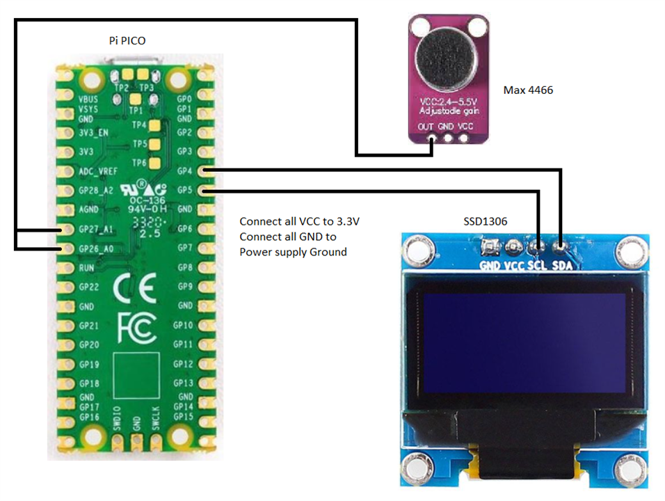
The hardware components used are PICO, Microphone MAX4466, and the OLED display SSD1306.
The Software Implementation: The code
Here I have used the Arduino IDE to code and flash.
#include <Arduino.h>
#include <U8g2lib.h>
#include <Wire.h>
#include "arduinoFFT.h"
#define R_IN 26 //R-input pin
#define L_IN 27 // L-input pin
#define PX1 62 // Left screen (L) Origin
#define PX2 65 // Right screen (R) Origin
#define PY1 16 // Bottom edge of waveform screen
#define PY2 55 // Bottom edge of spectrum screen (-50db)
arduinoFFT FFT = arduinoFFT(); // Create FFT object
U8G2_SSD1306_128X64_NONAME_F_HW_I2C u8g2(U8G2_R0, /* reset=*/ U8X8_PIN_NONE);
const uint16_t samples = 128; // number of samples
// Computational area of FFT (actually maybe 32-bit floating point?)
double vReal_R[samples];
double vImag_R[samples];
double vReal_L[samples];
double vImag_L[samples];
// Raw waveform data
int16_t wave_R[samples];
int16_t wave_L[samples];
void setup() {
pinMode(16, OUTPUT); //For execution time measurement
pinMode(25, OUTPUT); // pico built-in LED
Serial.begin(115200);
analogReadResolution(12); // Set ADC full scale to 12 bits
u8g2.begin();
u8g2.setFont(u8g2_font_6x10_tf);
u8g2.setDrawColor(1);
u8g2.setFontPosTop(); // The upper left is the character position
u8g2.clearBuffer();
u8g2.drawStr( 0, 0, "Start FFT v0.4");
u8g2.sendBuffer();
delay(1000);
}
void loop() {
digitalWrite(25, HIGH); // Built-in LED lights up during sampling
for (int i = 0; i < samples; i++) {
wave_R[i] = analogRead(R_IN); // Waveform data acquisition (fs: 4096) For Both the input L and R.
wave_L[i] = analogRead(L_IN);
delayMicroseconds(21); // Sampling cycle adjustment (1 cycle 39us)
} // (5ms)
digitalWrite(25, LOW);
// FFT calculation data preparation(1.7ms)
for (int i = 0; i < samples; i++) {
vReal_R[i] = (wave_R[i] - 2048) * 3.3 / (4096.0); // Converted to voltage
vReal_L[i] = (wave_L[i] - 2048) * 3.3 / (4096.0);
vImag_R[i] = 0;
vImag_L[i] = 0;
}
FFT.Windowing(vReal_R, samples, FFT_WIN_TYP_HAMMING, FFT_FORWARD); // Window function (hamming) application
FFT.Windowing(vReal_L, samples, FFT_WIN_TYP_HAMMING, FFT_FORWARD);
FFT.Compute(vReal_R, vImag_R, samples, FFT_FORWARD); // FFT
FFT.Compute(vReal_L, vImag_L, samples, FFT_FORWARD);
FFT.ComplexToMagnitude(vReal_R, vImag_R, samples); // Calculation of absolute value
FFT.ComplexToMagnitude(vReal_L, vImag_L, samples);
u8g2.clearBuffer(); // Clear screen buffer (22us)
showWaveform(); // Waveform representation (6ms)
showSpectrum(); // Spectrum display (9.4ms)
showOthers(); // Scale line and other display (1.6ms)
u8g2.sendBuffer(); // (30ms)
delay(1); // Magic of writing failure measures
} // (Loop execution time: 82ms)
void showWaveform() { // Input waveform display
for (int i = 0; i < 52; i++) {
u8g2.drawLine(PX2 + i, PY1 - (wave_R[i * 2]) / 256, PX2 + i + 1, 16 - (wave_R[i * 2 + 1] / 256)); // R-ch waveform plot
u8g2.drawLine(PX1 - i, PY1 - (wave_L[i * 2]) / 256, PX1 - i - 1, 16 - (wave_L[i * 2 + 1] / 256)); // L-ch waveform plot
}
}
void showSpectrum() { // Spectrum display
int d;
static int peak_R[64]; // Past peak value
static int peak_L[64];
for (int xi = 1; xi < 60; xi++) { // Spectrum display (0 is skipped)
d = barLength(vReal_R[xi]);
u8g2.drawVLine(xi + PX2, PY2 - d, d); // Right (R-ch) spectrum
u8g2.drawVLine(xi + PX2, PY2 - peak_R[xi], 1); // Right peak
if (peak_R[xi] < d) { // If the latest value is above the peak value
peak_R[xi] = d; // Update peak value
}
if (peak_R[xi] > 0) {
peak_R[xi] --; // Decay peak value
}
d = barLength(vReal_L[xi]); // L side spectrum display
u8g2.drawVLine(PX1 - xi, PY2 - d, d); // Left side (L-ch) spectrum
u8g2.drawVLine(PX1 - xi, PY2 - peak_L[xi], 1); // Right peak
if (peak_L[xi] < d) { // If the latest value is greater than or equal to the peak value
peak_L[xi] = d; // Peak value update
}
if (peak_L[xi] > 0) {
peak_L[xi] --; // Decade the peak value
}
}
}
int bar length(double d) { // Calculate the length of the spectrum graph
float fy;
int y;
fy = 14.0 * (log10(d) + 1.5); // 14 pixels at 10x (20dB)
y = fy;
y = constrain(y, 0, 56);
return y;
}
void showOthers() { // Graph modification (scale and other drawings)
// Area division line
u8g2.drawVLine(PX1, 0, 64); // L screen origin line
u8g2.drawVLine(PX2, 0, 64); // R screen origin line
u8g2.drawHLine(0, PY2, 128); // Spectrum bottom line
// Frequency scale (horizontal axis)
for (int xp = PX1; xp > 0; xp -= 5) { // L side 1kHz interval scale
u8g2.drawVLine(xp, PY2 + 1, 1);
}
u8g2.drawVLine(PX1 - 25, PY2 + 1, 2); // L 5k scale
u8g2.drawVLine(PX1 - 50, PY2 + 1, 2); // L 10k scale
for (int xp = PX2; xp < 127; xp += 5) { // R side 1kHz interval scale
u8g2.drawVLine(xp, PY2 + 1, 1);
}
u8g2.drawVLine(PX2 + 25, PY2 + 1, 2); // R 5k scale
u8g2.drawVLine(PX2 + 50, PY2 + 1, 2); // R 10k scale
u8g2.setFont(u8g2_font_micro_tr); // With a small font (3x5),
u8g2.setCursor( 7, 58); u8g2.print("10k"); // L side frequency display
u8g2.setCursor( 34, 58); u8g2.print("5k");
u8g2.setCursor( 58, 58); u8g2.print("0");
u8g2.setCursor( 67, 58); u8g2.print("0"); // R side frequency display
u8g2.setCursor( 87, 58); u8g2.print("5k");
u8g2.setCursor(110, 58); u8g2.print("10k");
// Spectrum level scale (vertical axis)
for (int y = PY2 - 7; y > 16; y -= 14) { // dB scale line (horizontal dotted line)
for (int x = 13; x < 128; x += 5) {
u8g2.drawHLine(x, y, 2);
}
}
u8g2.setCursor(0, 17); u8g2.print("0dB"); // Spectral sensitivity
u8g2.setCursor(0, 30); u8g2.print("-20");
u8g2.setCursor(0, 45); u8g2.print("-40");
u8g2.setFont(u8g2_font_crox1cb_tf); // With a slightly luxurious font
u8g2.setCursor(0, 3); u8g2.print("L"); // Channel display
u8g2.setCursor(119, 3); u8g2.print("R");
}
In the Next Blog, I will show the project's Working and also you can visualize the Frequency of the Sound.
For now Please wait for my next BLOG.