Hi, as I said in the first blog, the purpose of this work is to acquire the knowledge of Raspberry Pi Pico board and to start using it for simple applications. I will use these blogs to introduce my students to the use of this board and its programming. Obviously, let's not forget the theme of this contest, so we will also talk about sound.
Introduction
The sound is caused by pressure waves that propagate through the air, something very different from the “1” and “0” sequences that digital devices use. As in the case of other physical quantities, Nature uses analog quantities while our devices use digital quantities
The Raspberry Pi Pico has 4 inputs that can be used to interface with analog signals, such as electrical signals received from an analog microphone. The user can only use 3 since the fourth is reserved for use with the internal temperature sensor of the board and will therefore be used by the Raspberry itself.

Looking at the pinout scheme, already reported in the first blog, we will see that the 3 pins that we can use for the conversion are:
- ADC0 pin31 GP26
- ADC1 pin32 GP27
- ADC2 pin34 GP28
These 3 pins are the inputs of 3 analog-to-digital converters (ADCs). The ADCs of the Raspberry Pi Pico are 12-bit and therefore allow you to quantize the input signal using 4096 different levels (212 = 4096), a rather interesting quality for simple IoT applications.
The analog-to-digital conversion operation is quite complex and, in the board manual, we can see that the time required to acquire a sample is about 2µs, which corresponds to a sample-rate of 500 kS/s.
In this blog I would like to play a bit with the analog-to-digital converter, taking care of connecting the board and writing the code to use.
Let's try the Raspberry Pi Pico ADC
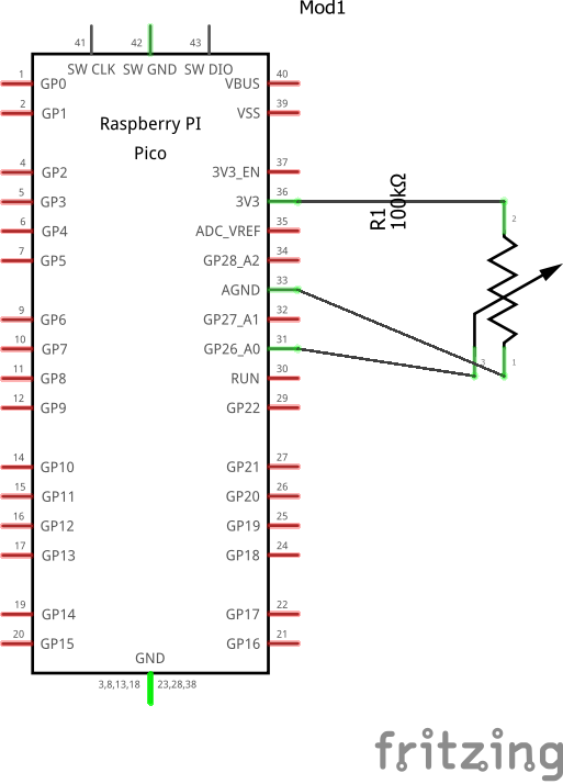
The simplest way to test an ADC is to use a potentiometer. Connecting the two lateral terminals respectively to GND and VCC, by turning the knob of the potentiometer, we will obtain on the cursor all the voltages between 0V (GND) and, in our case, 3.3V (VCC).
Potentiometer wiring diagram between pin 33 AGND and pin 36 3V3 (OUT), cursor on pin 31 AD0.


The code
As for the code, it is very trivial and could also be managed directly by Putty but, for convenience, we used another equally light, portable and effective software tool, namely the Thonny IDE.
It is a minimal IDE and does not have the advanced features of other software tools but, for a student, it is a fantastic tool due to its ease of use.
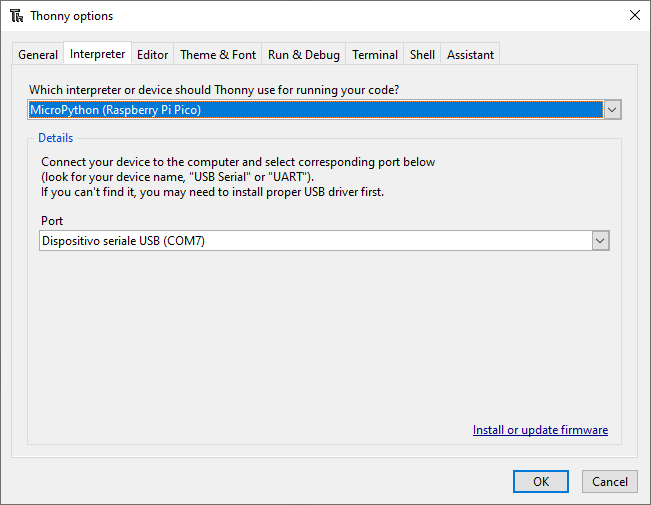
From the “Tools / Options” menu, going to the “interpreter” tab, you can configure the IoT board we are using and the COM port to which it is connected.

Let's see the code.
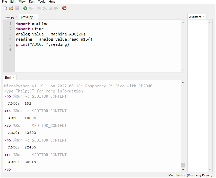
I import the modules I need:
import machine
import utime
I configure the ADC0 input:
analog_value = machine.ADC (26)
I read the voltage value on pin GP26 and display it:
reading = analog_value.read_u16 ()
print ("ADC:", reading)
Summarizing the code will be:
import machine
import utime
analog_value = machine.ADC (26)
reading = analog_value.read_u16 ()
print ("ADC0:", reading)

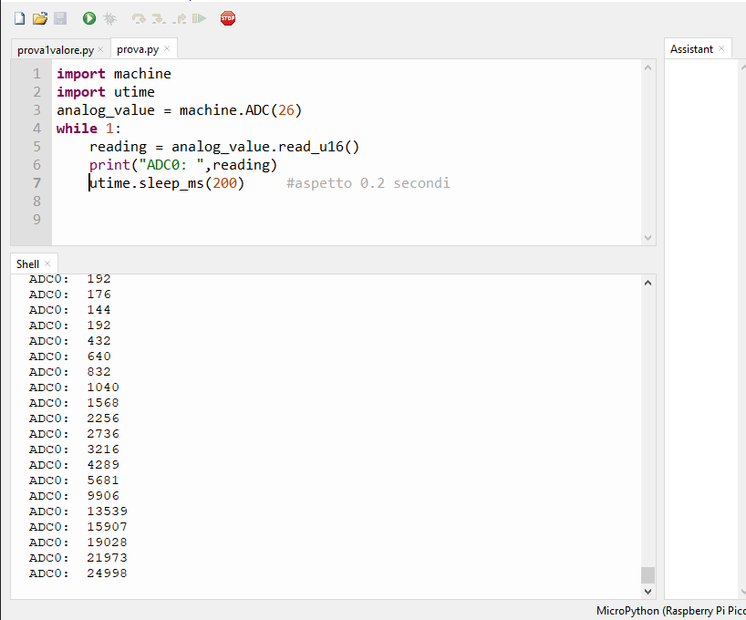
You can repeat the voltage reading on the potentiometer cursor indefinitely and then obtain the voltage values after a certain time, for simplicity I set the time at 0.2 seconds, setting a sleep time of 0.2 seconds
The code becomes:
import machine
import utime
analog_value = machine.ADC (26)
while 1:
    reading = analog_value.read_u16 ()
    print ("ADC0:", reading)
    utime.sleep_ms (200) #wait 0.2 seconds

We expect that, by turning the potentiometer from one extreme to the other, it will go from a minimum value of "0" to a maximum of "4096", since we are using a 12-bit ADC. In theory, therefore, since we will use two bytes to hold the captured binary value, we will only work in the range of values from 0 to 4096 and the values from 4097 to 16K will be unused.
In practice, however, by turning the potentiometer, you can see that all 16 bits are used and the printed values will go from 0 to 64K. This obviously is not a "miracle" but it is one of the features of the MicroPython that uses the two bytes entirely, obviously there will always be only 4096 different levels.
Coming soon we will see how to use a microphone with our Raspberry Pi Pico.
See you next blog!
