


Moving away from the OpenHAB interface config for a bit, I started working on the Feeder Control System that will drive the Feeder for my project. For this, I decided to use the Pi Face Display and Control as well as the Digital 2 connected to the Pi Face Rack. There were a couple of challenges using the Pi Rack with these devices and I will cover those in this post. With these devices, my intention was to create a manual means to enter and control the feeder system which will also interact with the OpenHAB interface.
Pi Face Pi Rack
The Pi Rack is very handy device to use with the Raspberry Pi which allows expandability of connections to the RasPi. However, there were a few things that I did run into that made the config a not so simple effort.
The first thing to note, and something I discovered after some searching, is that the Pi Rack is shipped (at least the one I have) with the jumpers to swap between SPI and CS lines in the reverse configuration. This seems to work fine when using only one device to the Pi Rack, but if you intended to use multiple devices each with a separate SPI addresses, the Rack will not work as is.
I did find this post to be very helpful : https://www.element14.com/community/thread/27170/l/pirack-problem?displayFullThread=true
Here be an image of the Jumper settings that work when using separate SPI addresses for the devices on the Pi Rack:
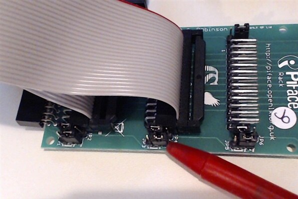
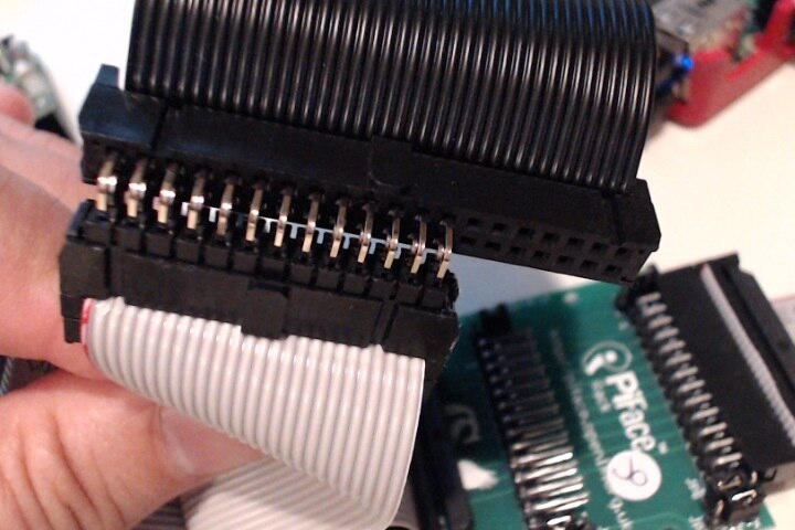
Another thing to note form the Image above, when using a ribbon cable with the Pi Rack, Is that with the Power Jumper on the one side of the 26 pin connection, and the SPI/CS jumpers on the other side of the connection, there is not much space to plug in the connector from the ribbon cable so you might have to move the jumpers over a bit. For the ribbon cables, I used the IDC 26 pin Dual Row Socket IDS-26-P connectors with 26 wires from a 40 wire ribbon cable since Fry's only had 25 wire ribbon cables but the 26 pin connector; strange.
Also, the reason I used the ribbon cables was that neither the Pi Face Digital 2 nor the Pi Face Display and Control would fit on the Rack. The Digital 2 has a 40 pin connection so that would not fit and the IR receiver and the Slider switch on the Display and Control got in the way, but in the end this allowed more flexibility with mounting the whole config.
Pi Face Digital 2
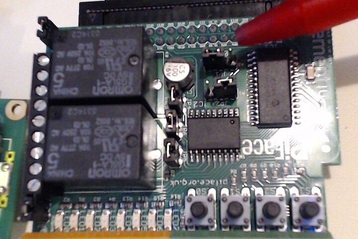
For my project, I am using the Pi Face Digital 2 to control the motor that will be used in the Feeder system to allow the Feed to be distributed. At this time, I am just looking at using the 2 relays on the board, but may using one of the outputs as well as a speed control.
In order to address the two Pi Face devices on the Pi Rack, since the Digital 2 has selectable jumpers on board, I set this device to 1 which left the Display and Control to 0.
To use the Digital 2 in a python script as I am doing, the Digital 2 libraries need to be imported.
import pifacedigitalio as pdio
To control the Relays on the Digital 2 (this is also tied to the LEDs on the board as well) I'm using the following commands in my runManual method:
def runManual():
    run_pin = 0
    stop_pin = 1
    pin_on = 1
    pin_off = 0
    clearDisplay()
    setDisplay()
    writeLine(2, 0, "Manual Run")
    print ("manual run")
    pdio.init()
    t.sleep(1)
    pdio.digital_write(run_pin, pin_on, 1)
    t.sleep(10)
    pdio.digital_write(run_pin, pin_off, 1)
    pdio.digital_write(stop_pin, pin_on, 1)
    t.sleep(5)
    pdio.digital_write(stop_pin, pin_off, 1)
    pdio.digital_write(run_pin, pin_off, 1)
I'll use the relays as an H-Bridge to control the direction of the DC Motor used in the Feeder system.
Pi Face Display and Control
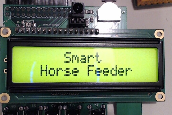
The Pi Face Display and Control will be used to Set Feed Timer, View Timer, Manual Run, and get Feed Status. I am using Python and the PiFace CAD libs to control the display and grab user input.
When first started, the display will show "Smart Horse Feeder" indicating the system is initializing.
I ended up mapping the port values to the switches and created a Dictionary for use with setting the Timer:
SW0 = 1
SW1 = 2
SW2 = 4
SW3 = 8
SW4 = 16
SW5 = 32
SW6 = 64
SW7 = 128

# Port to Button
button_dict = {SW0 : "Set Day",
               SW1 : "Set Hour",
               SW2 : "Set Min",
               SW3 : "Set AMPM",
               SW4 : "Select Mode",
               SW5 : "Down",
               SW6 : "Left",
               SW7 : "Right"}
The display will then prompt the user to select a mode from a selectable list controlled via the switches on the Display and Control device.
The default display is to show the current time with an arrow pointing to switch 4.
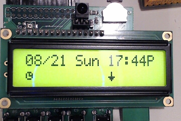
The timer and the arrow icons where created using a bit map based on the data listed at the following location:
http://www.quinapalus.com/hd44780udg.html
The python code looks like this:
timerBM = p.LCDBitmap([
0b00000,
0b00000,
0b01110,
0b10101,
0b10111,
0b10001,
0b01110,
0b00000])

arrow1BM = p.LCDBitmap([
0b00000,
0b00000,
0b00100,
0b00100,
0b00100,
0b11111,
0b01110,
0b00100])
When this switch is pressed, it takes the user to the Select Mode option.
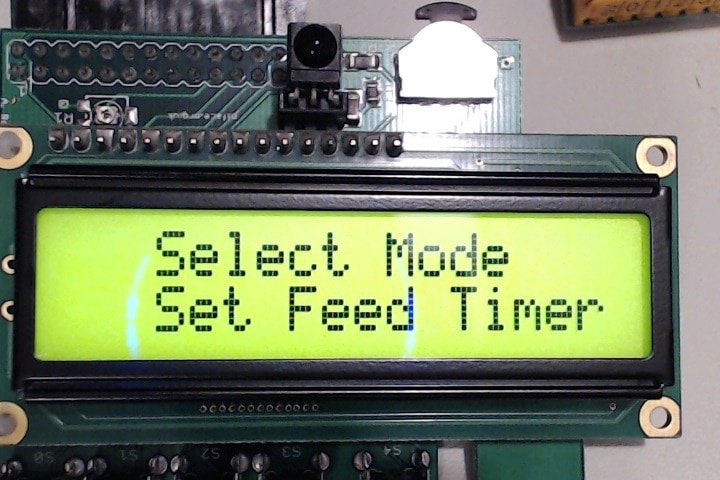
From here, the user can select between Set Feed Timer, View Timer, Manual Run and Feed Status. To keep track of the timer setting, I am using Json to dump and load a Dictionary to a .json file that I intend to use later to show in OpenHAB via MQTT.
def saveTimerData(timer_data):
    with open('timer_data.json', 'w') as outfile:
        json.dump(timer_data, outfile)

def getTimerData():
    if os.path.isfile('timer_data.json'):
        with open('timer_data.json') as data_file:
            data = json.load(data_file)
            return data
    else:
        return None
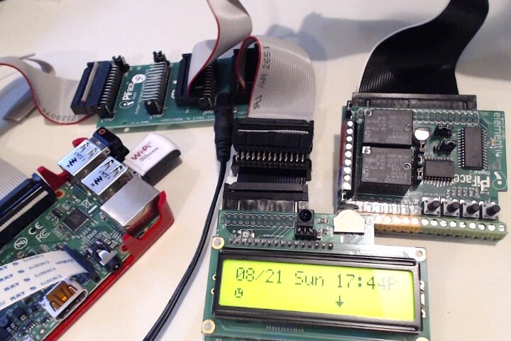
The config with cabling so far looks like this. I'll still have to get this in some sort of enclosure before the 29th:
In the end, the system works as follows.
Next steps are to get all the pieces working together and set in enclosures as well as complete the feeder system.
Top Comments