


<Work in progress, the attachments can be changed when the controller is done>
The idea for this part is to have a way to control the lights in the house from your phone, PC, or through a web address. Also the system let's you receive information about the current state of the light.
An important part is to leave the possibility to control the lights from the wall switches as before.
The whole controller for the switches should be as small as possible. To make it fit I had to dig a small hole in the wall below the switch to fit the relays, but the controller actually fits behind the switches.
Previous posts
Pi IoT - Simone - Introduction
To make this component the system is separated in:
- Main server
- Relay switches
- Lights controller
- Ammeter
Main Server
The main server is hosted on the raspberry PI and it is a C++ application that ensures the communication through I2C to the other components throughout the house, it keeps the current state of things and also provides the interface for communication through WebSockets for the phone to connect to.
This system will be covered in a later post as it is not fully functional at the moment and also it is a component on it's own in this project.
Relay Switches
To leave the possibility to control the lights in the old way I used a staircase switch connected to the relays board. The relays are RM50-3011-85-1005 which actually works as a staircase switch by changing the connection from the main pin to one of the two out pins. Here are some explanation of how to connect the switches: StairCase Wiring Circuit Diagram. Electrical Technolg
The relay board is supposed to be controlled by an Atmel Chip which cannot provide the power for the relays to function so I used a simple transistor system to digitally control them.
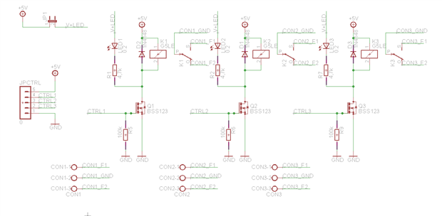
The schema is for three switches.
Lights controller
The lights controllers use a AT Tiny micro controller to ensure the connection to the main system through I2C and control the switches.
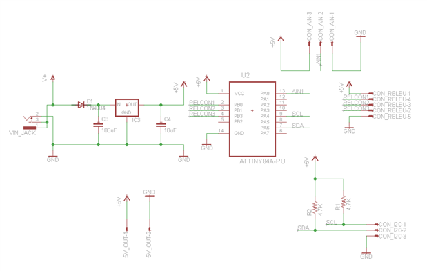
The component also has a voltage regulator because the ATTiny chip works on 5 volts and I sent 20 Volts through the cable to ensure that it provides a necessary 5 volts to all the components and also if needed it can have more power for motors for example.
The controller has two in pins for the I2C communication, three pins for the light switches and an IN pin for the ammeter.
The code for the controller is attached to the post.
Besides the actual control functions the component also have a ping and an identify function.
The ping is used for the main system to identify when a component has a notification and also that it has connection to the whole system. Because the I2C is a Master/Slave communication system and the ATTiny controller are not very fast, for notifications the main system pings all the known devices and checks if there are notifications to be communicated. The light controller does not have an alerting system nor does it need one but it seemed better the have the same interface working for all the components.
The Identification function is used by the main system to know how to control the component. The idea is to be able to connect one now controller to the system without actually "telling" the server on the Raspberry that you did so and how to control it. The identification is a simple string that has the I2C address, how many switches it controls and what type of a controller it is.
Ammeter
The issue with the system is actually the part where normal functions should be provided to the user, so the system can switch lights through the phone but the user can also use the actual switches on the wall which are not digital, but normal ones. This way if there is an error the light can still be switched on and also it lets visitors turn on the lights even if they do not have permissions to control the devices. I think an important part for the system is to make life easier and not change it all together.
When the light is turned on from the switch and not from the device the system needs to know so it can tell you if it is on or off. Also the relays can switch between two positions. If the light is on the switch will turn it off and vice versa.
Taking into consideration that if you have multiple switches, the possibility for them to control the same power consumption is very low. So I am building an ammeter to calculate which lights are on and which are off. So I will try to calculate the power consumption on the mail cable that goes to the switch and after that calculate which lights are on and which are off. If there are changes in the system a simple calibration process can be made where the user is asked to turn on the lights one by one and the component gets the data for each switch. This is what I am trying at the moment as a basic low cost ammeter:
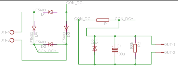
This component is not ready yet. At this moment I am building this schema and I will test it. If everything works tomorrow I should be able to continue this post and have a working system for the light switches. If there is anyone who has a better idea please leave it in the comments.
Top Comments