


Back to posting new entries after a long long silent period.... I will try to catch up with my original schedule in the next days, let's go!
In this entry, I will be focusing in the “Sensors Node” of the smart house. As some may suspect, I will be explaining how the house generates data (from a set of sensors: temperature, pressure, door open/close), which can be distributed to various clients. In this architecture, sensors are wired to the node (Raspberry Pi 1), which is in charge of:
- Fetching data from each sensor (a complete list of sensors is presented in next sections)
- Publish this data to the “Central Node” (Raspberry Pi 3). To do so, the Sensors Node implements an MQTT client to be publishing this content to the MQTT broker(*) in the Central Node.
(*)Previous post described installation and setting up of MQTT broker, Mosquitto, in a Raspberry Pi 3.
Furthermore, a subscriber MQTT client is built in the Central Node, to display the read data in a terminal interface. The other MQTT client will be developed in a smartphone, so the user can access the information directly from their handheld device.
All MQTT clients are implemented using Paho, which provides libraries in Python (used in Sensors Node and Central Node scripts) and Java (used in the smartphone application)
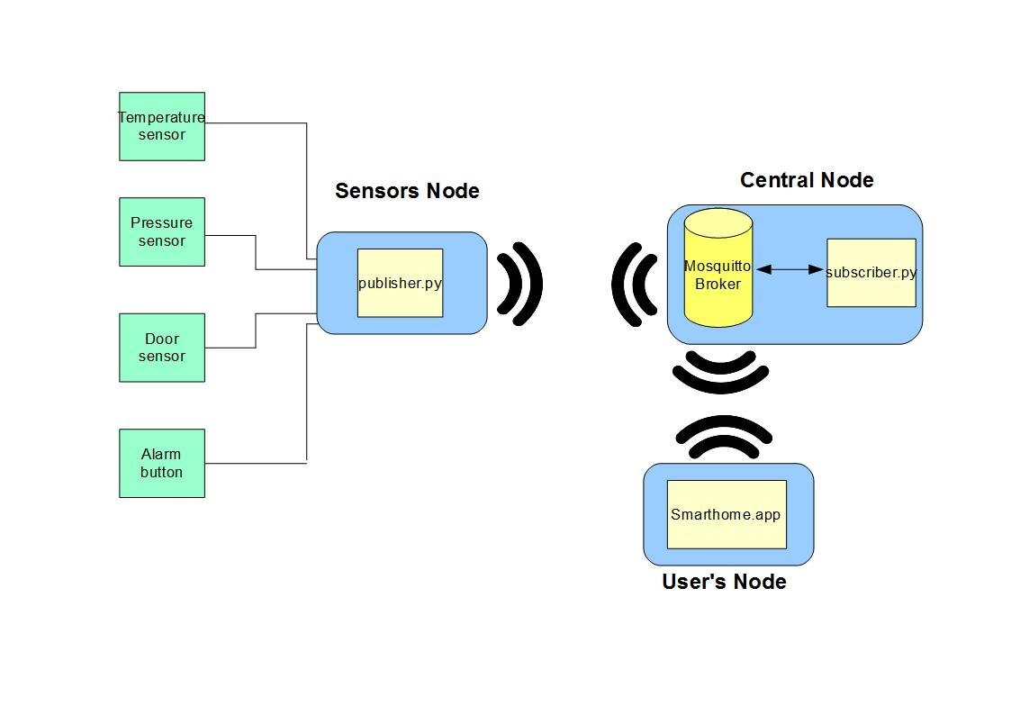
Wireless communication among nodes is achieved using the same home WiFi network.
Sensors Node: an MQTT publisher client
Initial setup: Raspberry Pi 1- Raspbian 8.0 (jessie) / SSH connection enabled
The sensors node is the main source of information of the smart house. Instead of having independent, autonomous and wireless sensors which can directly send their information to the Central Node, I am using simpler devices that have to be directly connected to a microcontroller. Since the Central Node should not be dependent on where these sensors are located, I include a new node "Sensors Node" (a Raspberry Pi).
Is a fully automated sensors system? Well... not that much: other approaches present each sensor as its own device, which can be accessed remotely without the need of any intermediate node. This version, however, show a cheap, fast to build platform which, in highly populated systems, could serve to reduce wireless interference (by having several sensors wired up to one node, instead of wirelessly connected).
List of elements and sensors
Element | Device |
Microcontroller | Raspberry Pi |
Temperature Sensor | TMP006 |
Pressure Sensor | MPL3115A2MPL3115A2 |
Door Sensor | Magnetic switch |
Alarm button | Switch |
Hardware connections
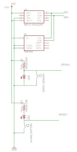
The following figures represents the schematics of the Raspberry Pi 1 node. It features its 4 sensors and the corresponding Raspi 1 GPIO port they are connecting to.
Temperature and Pressure sensors
Our temperature and pressure sensors are both connected to the I2C ports of Raspberry Pi 1, SCL and SDA.
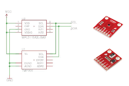
The I2C protocol only needs two buses to connect several sensors together. Each individual component is identified by a unique byte-size address. In our case:
- Temperature sensor - Ox40
- Pressure sensor - Ox60
We want to emphasize that, even if we are using these default addresses, both chips are designed with two extra inputs which can define new addresses. Thus, we can have more than one of each of these sensors in the platform (for example, distributed among the rooms).
Door Switch & Alarm button
Alarm and door switches each will use a dedicated GPIO port. They both behave as switches, although they present opposite type of behavior.
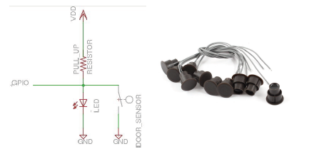
DOOR SWITCH:
This switch works following a usually closed behavior. When the sensor is embedded in a magnetic field, it will stay closed. When there is not such a field, it behaves as a short circuit.
This door switch is usually sell with two parts: a magnet and the sensor to be wired in the control system. Each part will be located at different parts of the door itself. The magnet will be placed in one side of the door, whereas the sensors is at the doorjamb. This way, when the door is closed both parts are facing each other (magnetic field affecting the sensor), though when it opens they separate (with no magnetic field around, the sensor will open the circuit, providing a 1 for the digital input).
We include a LED in the circuit, to have a visual confirmation when the door is open.
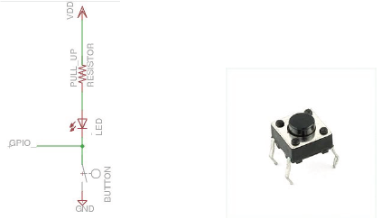
ALARM BUTTON:
This switch works following a usually open behavior. It will be open by default, and when the button is pressed the circuit will be closed. For this reason, the schematic implemented has the button between the GPIO port and ground. The digital input will be showing a 1 at its entrance until the button is closed (it
will connect to ground and change to 0).
Again, visual confirmation is included with a LED.
Software implementation

Initial setup: Raspberry Pi 1- Raspbian 8.0 (jessie) / SSH connection enabled
In the sensors node, there is a Python script running to read the sensors information and deliver it to the central node. The code can be found in
https://github.com/clazarom/SmartCompetitionHome_2016/tree/master/Sensors%20Node/Python
I made use of the Adafruit project, to read the temperature sensor: they have very complete libraries for several libraries, including the TMP006. The pressure sensor also have available libraries in Python, such as this MPL3115A2.py . Additionally, Paho libraries are imported to creat the MQTT client.
NOTE: Both Paho and Adafruit will require some module to be install for Python:
PAHO - run the command sudo pip install paho-mqtt
ADAFRUIT - make sure the gpio module is install. Run the command sudo pip install rpi.gpio
There are three main python files in the project:
- publisher.py - the main python file. It deploys the MQTT client and read sensor functions. It works as an infinite loop, which in each iteration fetches new data from the sensors and sends it to the broker
- TMP006.py - manages temp sensor
- MPL3115A2.py - manages pressure sensor
- door_controller.py - includes door sensor and alarm button
Sensors reading
I2C Communication
Files: publisher.py, TMP006.py and MPL3115A2MPL3115A2
The python program in the Raspberry Pi (publisher.py) uses some Adafruit libraries to interact with the sensors. Using their default addresses, it will first initialize each of them, and then read the input data periodically. The information obtained is:
- From the temperature sensor: temperature of the room and temperature of the device
- From the pressure sensor: pressure of the room and altitude.
GPIO digital inputs reading
Files: publisher.py and door_controller.py
The program will be reading either 0 or 1 from the door and alarm button. We will also choose to of the GPIO pins to connect to them. In each case:
- Door sensor: GPIO pin 22* | Behavior: 1 door open/ 0 door closed
- Aalarm button: GPIO pin 27* | Behavior: 1 / 0 button pressed
*Using GPIO mode BCM
door_controller.py functions to state of door and alarm button:
#Pins number:
door_pin = 22
inc1_pin = 27

#Set pins
GPIO.setup(door_pin, GPIO.IN)
GPIO.setup(inc1_pin, GPIO.IN)
#GPIO.setup(inc2_pin, GPIO.IN)

#Function to read the door state
def check_door():
    #Read input value
    input_state = GPIO.input(door_pin)
    return input_state

#Function to read any of the two other incidents
def check_inc(input):
    #Check either pin
    input_state = 0
    if input == 1:
        input_state = GPIO.input(inc1_pin)
    else
        input_state = -1
    return input_state
Data Delivery
Files: publisher.py
The sensors node will also implement an MQTT client. The data already collected from the sensor will be published with MQTT. We define a MQTT publisher client. It will be sending data messages categorized as “sensors/type_sensor” topics.
In the same python program that is fetching data, we import Paho Python’s library and create a publisher. This publisher will:
- Connect to the broker. We used its local IP address(*) to send a connection request.
- Publish messages containing:
a) Data from the device
b) Topic representing each sensor
(*)This local IP address is hardcoded in the program an needs to be change every time we connect to a new network or Raspberry PI 3 is restarted. Next version of the code will have a scan kind of option to show the user available devices in the WiFi and select the correct one
Fragment of the publisher.py, the loop:
#Loop to read and publish
while True:
    #Read sensors
    #DOOR
    door = door_sensor.check_door()
    door_state = "unknown"
    if door == 0:
        door_state = "closed"
    elif door == 1:
        door_state = "open"
    print("Door: "+ door_state +" - "+  str(door))
    client.publish(id+"/"+d_topic,str(door) +" "+door_state)
    #WARNING
    warning = door_sensor.check_inc(1)
    if warning == 0:
        client.publish(id+"/"+w_topic, "!!!")
        print ("!Warning: "+ str(warning))
    #TEMPERATURE
    obj_temp = temp_sensor.readObjTempC()
    die_temp = temp_sensor.readDieTempC()
    client.publish(id+"/"+"devTemp", str(obj_temp) +" C")
    client.publish(id+"/"+t_topic, str(die_temp)+ " C")
    #PRESSURE
    pres_sensor.calibrate()
    pressure = pres_sensor.pressure()
    altitude = pres_sensor.altitude()/100
    client.publish(id+"/"+p_topic, str(pressure)+ " Pa")
    client.publish(id+"/"+a_topic, str(altitude)+" meters")
    time.sleep(1.0)
d_topic, t_topic, p_topic and a_topic are of the type "sensors/sensor" (sensors/door , sensors/temperature ...)
Other clients
Central Node subscriber
Initial setup: Raspberry Pi 3 - Raspbian 8.0 (jessie) / SSH connection enabled / Mosquitto MQTT broker installed
https://github.com/clazarom/SmartCompetitionHome_2016/tree/master/Central%20Node/Python
Files: subsciber.py and console_interface.py
The first subscriber MQTT client will be ont he broker. It has two main functions:
- Verify the correct functioning of the sensor node and other publishers
- Display publishers data in the main GUI of the platform
- Fetch data from the publishers to:
- Store in a database
- Other uses
Again, we use Paho libraries and create a python script subscriber.py to implemente the MQTT client. It will connect to the broker (local, to itself) and subscribe to the topic "sensors/#" (to read the infro published by Sensors Node).
In order to display this information, we created a console interface console_interface.py. Using curses, we can define the visual of our screen. This program shows a boxed table which will be updating its data with every new incoming data. Other information is displayed, such as the result of the connection to the broker or key iteractions with the program.
publisher.py code for the call back on message received:
def on_message(client, userdata, msg):
    #print(msg.topic+ " " + str(msg.payload))
    content = str (msg.payload)
    topic = str(msg.topic)
    #Evaluate message:

    if (topic == "sensors/temperature"):
        console.update_values(screen, console.TEMP_POSITION, content)
    elif (topic == "sensors/devTemp"):
        console.update_values(screen, console.TEMP_POSITION + 1, content)
    elif (topic == "sensors/pressure" or content.find("Pa")!= -1):
        console.update_values(screen, console.PRES_POSITION, content)
    elif (topic == "sensors/altitude" or content.find("meters")!= -1):
        console.update_values(screen, console.ALT_POSITION, content)
    elif (topic == "sensors/door" or content.find("door")!= -1):
        console.update_values(screen, console.DOOR_POSITION, content)
    elif (topic == "sensors/warning" or content.find("warning")!= -1):
        time = datetime.datetime.now()
        time.isoformat()
        console.update_values(screen, console.ALARM_POSITION, "!! ALARM : "+ str(time))

    screen.refresh()

    #Check if there is any user input
    if (console.get_char(screen)):
        client.disconnect()
        print("Disconnect")
Smartphone subscriber

Initial setup: Smartphone - Android 4.2.2
https://github.com/clazarom/SmartCompetitionHome_2016/tree/master/Smartphone%20Apps/SmartHome_Client
It would be very convenient for the residents to have an app in their own smartphone to access the smart house system. Consequently, I developed the first version of the same: an app which works as another MQTT subscriber client. Smarthome_Client apk
We still use Paho libraries, as there is also a Java version which works perfect for Android apps.
At this point, the smarthome application is only able to read the information sent from the sensor node. In the future, this application should be able to interact with the system. Send some command, set up some parameters etc. Moreover, the game-competition part of this project will also have an Androidd application to monitor each individual progress, and will be added to the "Smart home application".
Results
We start our three nodes, verify the local IP addresses used and let the information flow.
To test that everything is working as expected, we check the subscriber client in the central node. Let’s see what happens when the system is up:
The video shows two terminals connected thru SSH to each of the Pi:
- Left terminal - Raspberry Pi 3 "Central Node": implements the MQTT subscriber
- Right terminal - Raspberry Pi 1 "Sensors Node": implements the MQTT publisher
Conclusion
We have set up a simple, yet complete functional infrastructure for our smart home. This system only reads some environmental and house state data, which can be viewed in the Central Node of the house, or with an App in the smart phone.
***********************************************************************************************************************************************************************************************************
The full code of the project can be found at:
Top Comments