Prior posts in the PiCasso Design Challenge:
PiCasso Design Challenge - Kinetic Art Mobile - Post 1
PiCasso Design Challenge - Kinetic Art Mobile - Post 2
PiCasso Design Challenge - Kinetic Art Mobile - Post 3 - Will it go round in circles????
As Dubbie (dubbie ) had pointed out in the comments section of my last post, my orbs do in fact look a lot like the Death Star. Recently I was performing some tests on the orb attached to my test setup, characterizing the effects of current limiting, to determine if this would be an effective method of controlling fan speed (In the past I have done a slow PWM, turning the fan on/off to create a 'slow' fan speed). The data looks promising, so I am currently working on the design of the orb controllers. Later than evening, after collecting data, I was watching TV when there was a disturbance of the force, coming from by office. At first it was a sort of strange rustling sound, but soon followed by a large 'crash'. The 'Death Star' crashed to the ground, shattering the orb and mangling the aluminum support rods. This was a tiny set back, as I was already down the road with a new design (which was shelved and restated - see below).
I had hoped to get a bit more data on by fan control/speed tests, but I do feel that I have a reasonably close understanding of the data. The power supply that I was using has a pretty course setting in the area of 10ma, so there was a lot of difficulty in stepping through current limits, producing some wildly different readings as I made multiple attempts to collect the data. There was also a bit of a difference in the speeds between the two direction (CW and CCW), which could be attributed to either the current settings, fan differences, directional changes in friction if the slip ring/test setup, etc. Given all that, the relationship between fan current and orb speed seems to be fairly linear.
The largest difference between the two tests was the point at which 'stalling' occurred. Clockwise, the orb continued to move at 80mA, where counter-clockwise, the orb stalled at 80mA. Either way, I was able to achieve a 6:1 or 4:1 orb speed range, which should allow for some interesting movements. The plan is to have a 3-axis accelerometer and magnetometer on board with each orb, so I will hopefully be able to control the fans to achieve a fixed speed, navigate to a fixed position and to detect and prevent stalling (more on this in future updates).
So, with my only functional prototype broken, it was time to work on my next orb design. As I started the latest design, I had a couple of areas that I wanted to focus on.
1) I wanted a cleaner design, with fewer blemishes in the orb exterior.
2) I wanted to clean up the orb interior, to make more room for electronics and to reduce any shadows due to bosses on the interior.
3) I wanted to increase the diameter of the orb a bit to again make room for more electronics and to find a good way to evenly place the LEDs inside the orb so the 'spinning effects' or 'chase patterns' would appear smoother.
So given these goals, I came up with the following designs:
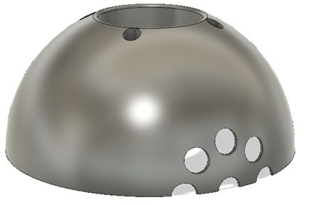
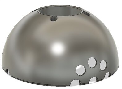
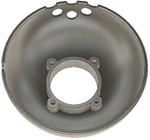
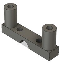
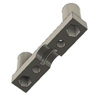
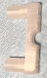
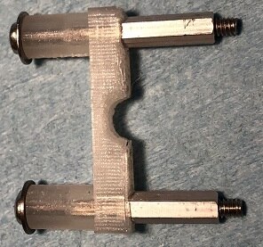
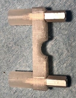
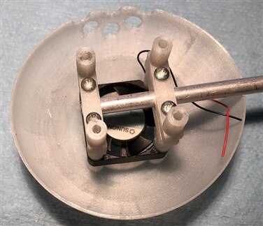
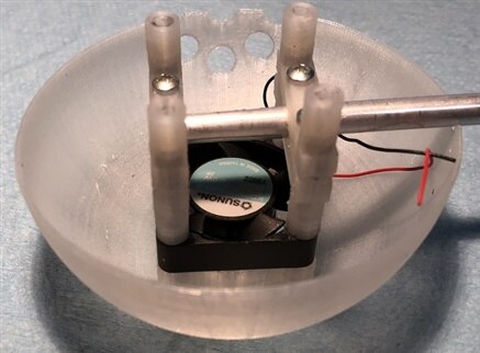
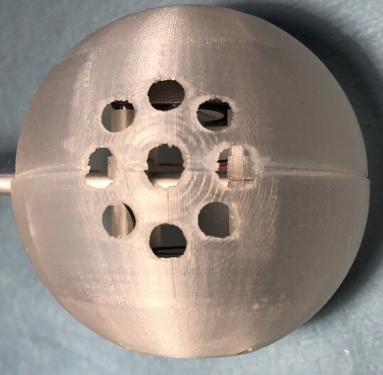
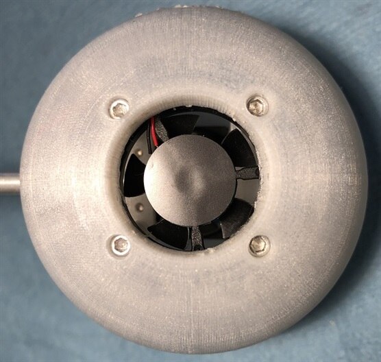
The Orb skin is thinner (0.025"), with air intake holes at the top of the orb (out of view), with only the fan mount on the interior (first three images). The two halves of the orb interlock as the raised lip of one seats into the other half of the orb. The rod retains have hex inserts (bottom) to accept hex standoff, with a rod grip surface (with flare capture groove) to tightly grasp the aluminum support rod. The unit assembles with 0.85" 2/56 screws, entering through the fan mounting holes and screwing into the embedded hex standoff in the rod retainer, from each side of the orb. Here are some pictures of the parts and the assembly process.
These images show the assembly process. The standoffs are pressed (pulled) into one side of the rod retainers (first three images). The second half is assembled in a similar process (while capturing the support rod), and the self taping screws are attached. Then the fan screws are fed through the orb skin, through the fan mountings and threaded into the standoff (embedded in the rod support assembly). Here are two views of the first half of the orb, with the rod support attached (last two images).
This update brings me pretty much current on my design challenge entry. I am now working on the design of the orb electronic (schematic and PCB). I see the final electronics design to include 3 PCBs (top, bottom and side looking LED strips to bridge the top/bottom). The top and bottom boards are intended to mount above and below the two fans (either round or rectangular PCBs, illuminating the top/bottom of the orb) with the LED strips to tie the two PCBs and illuminated the sides of the orb.
Thanks for reading along. This has been another fun adventure here in the universe of element14.
Gene


Top Comments