


The following images shows the steps of the creation of the Meditech HeartBeat probe electronics.
Schematics and layout
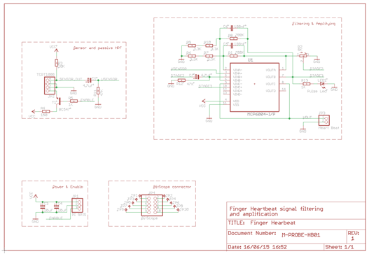
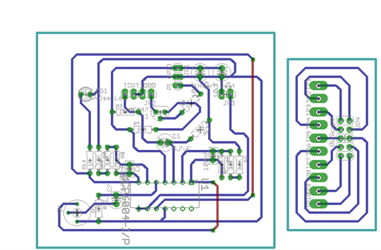
Above: schematics and layout of the probe.
The right side block (in the layout image), corresponding to the bottom right part of the schematic is a separate component; it is a small adapter to plug in the BitScope inputs for data acquisition from the various Meditech probes that plan to use analog and logic data prodcessing.
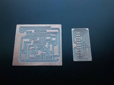
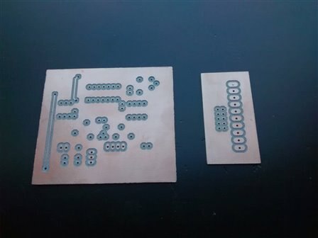
The two images below shows the resulting milled PCB (both sides)
Circuit assembly and connections
The images below shows the BitScope connector and how it will fit in the device.
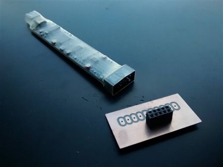
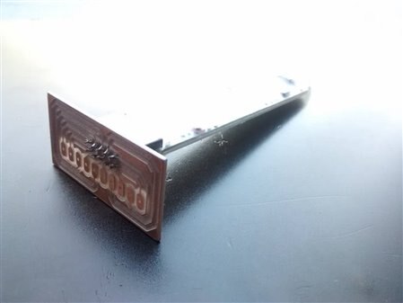
Below: the HearBeat circuit completed connected to the BitScope via the adaptor connector.
The led and sensor connector will be fices inside the working panel of the Meditech box.


