


Introduction
While waiting for some last components to finish building the last remaining probes the last days was busy for single parts testing and organising the components in their final asset.
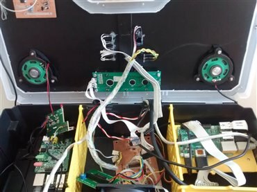
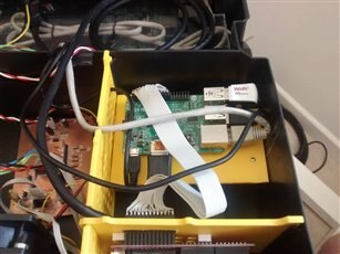
The resulting aspect of the Meditech prototype at the actual date is shown in the following image.
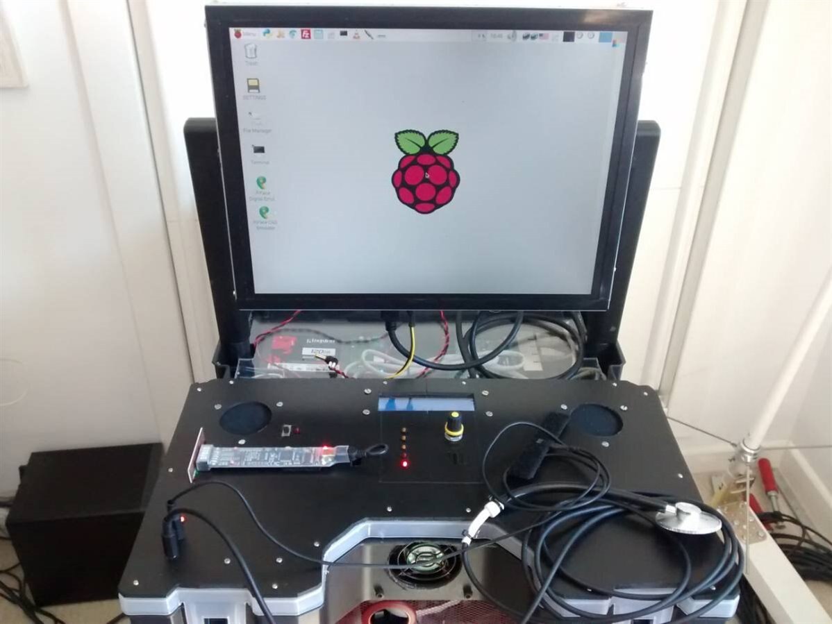
From top of the black plane you can see:
- Leftmost and rightmost circular holes hosts the two speakers for all the audio information and messages.
- Top-center the LCD 20x2 alphanumeric display. The display will survive in almost any condition as it is controlled by the PIC of the ChipKit PI that communicates with the PI Master but manages independently alarms and the entire control panel (temperature, menu, alarms and the general health status of the system.
- To the center below the display there is the notification LEDs column; three orange LED shows the status of the blood and hearth probes (when enabled), one LED will flash in synch with the IR controller and one dim its brightness depending on the cooler fan speed.
- To the center below the display (right side) there is the generic analog potentiometer that will be used for fast and reliable fine-tuning, with different behaviour depending on the active features.
- Below the potentiometer (not visible, as it is black on black) there is the IR sensor for the IR control of the system.
- Below the left speaker hole there is the BitScope set for probes data acquisition and already connected internally to the Raspberry PI
- The two bottom-left cables are connected respectively to the microphonic stethoscope and the heartbeat sensor
- To the front-side you can see the cooler fan
Actually missing are the GPS unit, the ECG device and the echo-unit, the high precision temperature checker and the blood pressure sphygmomanometer.
Settings and changes in detail
Storage final replacement
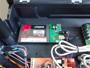
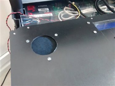
As described in the original design Meditech storage has been replaced with its definitive 120 Gb SSD storage. The reason adopting an SSD is not too much related to the higher speed of the SSD respect the traditional HDD: as a matter of fact the SSD is connected to the Raspberry PI through a USB 2 and the speed increase is not so meaningful. Very important instead is the reduced weight and the greater resistance of the SSD devices respect their mechanical cousins especially for an architecture that will be used in unpredictable situations.
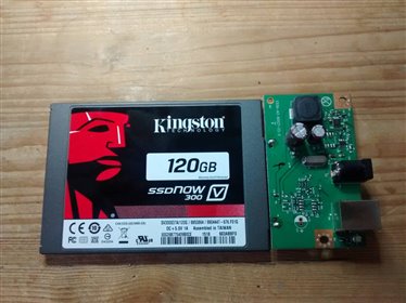
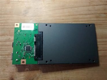
The image shows the SSD installed after the removal of the temporary 1TB 5" HDD
It is possible to connect external storage to the Raspberry PI via one of the USB 2 ports. I have searched for a mSATA to USB adapter but I have not found nothing of reliable so I have bought a 120 Gb SSD with the standard SATA adapter instead of the smaller mSATA and reused a spare board SATA-to-USB adapter usually connected to mechanical HDD.
In the post Raspberry PI: USB hard disk boot I have discussed how to setup an external HDD to be used as system disk on the Raspberry PI.
After formatted the SSD and partitioned with ext4 format (see the mentioned post for details) all the existing data from the old HDD has been transferred with the rsynch terminal command to the new SSD drive. Then the system has been powered down, the HDD has been definitely removed and booted with the SSD without problems.
Speakers
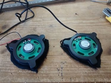
For the speakers a simple amplified stereo circuit for PC has been used. The two speakers, after some hearing tests has been set in a strategic position considering the expected position of the operator during while he is working in front of the Meditech device.
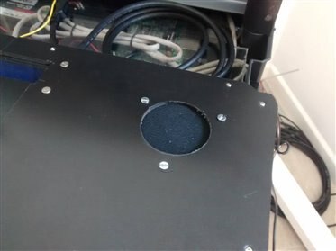
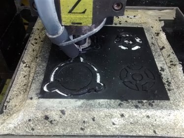
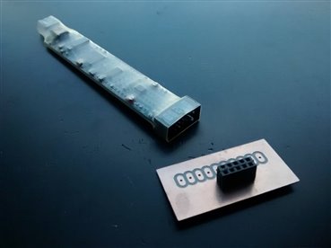
To set the two speakers, as usual a two-parts support has been designed then milled on a 3mm thick plastic plate as shown in the following images.
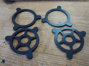
The exposed surface (top speaker side) has been covered with a soft fabric then the two support has been screwed under the two surface holes.
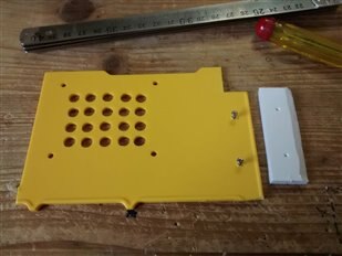
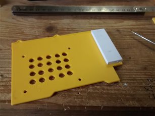
Freeing some space
For a better air circulation and to fit the wires in a more rational way the PI master device has been rotated modifying the support as shown in the images below. The temperature sensor of the control panel detect the average temeperature between the Raspberry PI board and the yellow support.
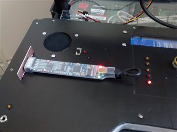
Installing the BitScope
Using the simple adapter circuit for the BitScope probe headers the device has been installed on the top surface of the control panel. This method has the advantage to save a lot of time, avoiding an excessive modification to the original BitScope device and in the meantime exposing the led and status signals so they are immediately visibile to the user.
Unsolved speakers issue
As you can see in this short example, the speakers generates a very disturbing noise. This occurred as I powered the system for the first time, so I though in something wrong in the circuit, connections etc. Instead all was fine. After doing some tests I discovered that this noise - persisting also when the audio board is not playing - occurs only when the HDMI cable between the PI and the monitor is disconnected. As I plug the cable in the monitor I got a perfect silence. The noise restarted as the monitor was powered on.
Note also that the HDMI cable connected the PI master device that is a different one than the PI Slave 4 hosting the audio card. I have no idea what I should check to stop this problem. Any suggestion is welcome.
Top Comments