element14 Community
element14 Community
    Register Log In
  • Site
  • Search
  • Log In Register
  • Community Hub
    Community Hub
    • What's New on element14
    • Feedback and Support
    • Benefits of Membership
    • Personal Blogs
    • Members Area
    • Achievement Levels
  • Learn
    Learn
    • Ask an Expert
    • eBooks
    • element14 presents
    • Learning Center
    • Tech Spotlight
    • STEM Academy
    • Webinars, Training and Events
    • Learning Groups
  • Technologies
    Technologies
    • 3D Printing
    • FPGA
    • Industrial Automation
    • Internet of Things
    • Power & Energy
    • Sensors
    • Technology Groups
  • Challenges & Projects
    Challenges & Projects
    • Design Challenges
    • element14 presents Projects
    • Project14
    • Arduino Projects
    • Raspberry Pi Projects
    • Project Groups
  • Products
    Products
    • Arduino
    • Avnet & Tria Boards Community
    • Dev Tools
    • Manufacturers
    • Multicomp Pro
    • Product Groups
    • Raspberry Pi
    • RoadTests & Reviews
  • About Us
  • Store
    Store
    • Visit Your Store
    • Choose another store...
      • Europe
      •  Austria (German)
      •  Belgium (Dutch, French)
      •  Bulgaria (Bulgarian)
      •  Czech Republic (Czech)
      •  Denmark (Danish)
      •  Estonia (Estonian)
      •  Finland (Finnish)
      •  France (French)
      •  Germany (German)
      •  Hungary (Hungarian)
      •  Ireland
      •  Israel
      •  Italy (Italian)
      •  Latvia (Latvian)
      •  
      •  Lithuania (Lithuanian)
      •  Netherlands (Dutch)
      •  Norway (Norwegian)
      •  Poland (Polish)
      •  Portugal (Portuguese)
      •  Romania (Romanian)
      •  Russia (Russian)
      •  Slovakia (Slovak)
      •  Slovenia (Slovenian)
      •  Spain (Spanish)
      •  Sweden (Swedish)
      •  Switzerland(German, French)
      •  Turkey (Turkish)
      •  United Kingdom
      • Asia Pacific
      •  Australia
      •  China
      •  Hong Kong
      •  India
      • Japan
      •  Korea (Korean)
      •  Malaysia
      •  New Zealand
      •  Philippines
      •  Singapore
      •  Taiwan
      •  Thailand (Thai)
      • Vietnam
      • Americas
      •  Brazil (Portuguese)
      •  Canada
      •  Mexico (Spanish)
      •  United States
      Can't find the country/region you're looking for? Visit our export site or find a local distributor.
  • Translate
  • Profile
  • Settings
Sci Fi Your Pi
  • Challenges & Projects
  • Design Challenges
  • Sci Fi Your Pi
  • More
  • Cancel
Sci Fi Your Pi
Blog Meditech: The power distribution
  • Blog
  • Forum
  • Documents
  • Files
  • Mentions
  • Sub-Groups
  • Tags
  • More
  • Cancel
  • New
  • Share
  • More
  • Cancel
Group Actions
  • Group RSS
  • More
  • Cancel
Engagement
  • Author Author: balearicdynamics
  • Date Created: 28 May 2015 9:15 AM Date Created
  • Views 880 views
  • Likes 1 like
  • Comments 4 comments
  • power_rail
  • meditech_project
  • power_unit
  • power_distribution
  • power_switch
  • raspberry-pi
  • atx
Related
Recommended

Meditech: The power distribution

balearicdynamics
balearicdynamics
28 May 2015

Introduction

In the Meditech container there is a variable number of devices working at least at two different voltages: 5V and 12V. In this prototype version the definitive powering system has been moved to the bottom of the priorities due the restricted deadlines and the need to have an experimental unit before a final decision: battery type, charging type, power consumption etc. Just for this reason the power will be granted by a common ATX switching power supply. This implies a couple of conditions:


  • For any future change, we will grant a power distribution for 3,3V, 5V, 12V
  • The number of power points is variable and should not be difficult to increase / decrease
  • The main power should be simple to be replaced as in future the power source is different than the first prototype


Main power module

The main power module simply act with a NE555 in a similar way as the logic power switch of PCs. This is a small independent circuits that should be replaced by the future battery power control.

The following images shows the circuit schematics and the relative layout.


imageimage


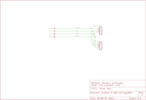
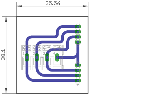
Power rail distribution

Every powering unitis a short module that will fit in a plastic rail; the circuit can be positioned along the wider side of the bottom of the Meditech box for easy reachability of the powered devices. Every group is connected with the previous and exposes all the power supply voltages and ground.

The following images shows the circuit schematics and the relative layout.


imageimage

  • Sign in to reply

Top Comments

  • Former Member
    Former Member over 10 years ago in reply to balearicdynamics +1
    Thanks! I had assumed as much, I knew that the wires needed to be connected for the powerpacks to run but it's the first time I've seen this solution!! Is there an ideal duty cycle for the pulse? Luci…
  • balearicdynamics
    balearicdynamics over 10 years ago in reply to Former Member

    Lucie,


    I think that the following link has all what you need: http://pinouts.ru/Power/atxpower_pinout.shtml


    Cheers Enrico

    • Cancel
    • Vote Up 0 Vote Down
    • Sign in to reply
    • More
    • Cancel
  • Former Member
    Former Member over 10 years ago in reply to balearicdynamics

    Thanks!


    I had assumed as much, I knew that the wires needed to be connected for the powerpacks to run but it's the first time I've seen this solution!! Is there an ideal duty cycle for the pulse?


    Lucie

    • Cancel
    • Vote Up +1 Vote Down
    • Sign in to reply
    • More
    • Cancel
  • balearicdynamics
    balearicdynamics over 10 years ago in reply to Former Member

    I was expecting this question just from you or few others image


    Well, reading on the net there is a lot of documentation on the use and advantages of the ATX power suppliers, stable and reliable. You also read a lot that to power on it is sufficient to shortcut two cables, put a simple button and so on. But: why PCs uses a logic to power them? You see too that this barbaric method to power with shortcut (in the better cases they suggest a resistor instead of the direct shortcut) shorten the life of the ATX. What it is needed is a pulse, one in one direction to enable the powering and one in the opposite direction to disable it. So - as I love 555 that was my heroes while I was child - instead of something too complex, this 555 configuration for few cents works perfectly simulating the same push-button for PC power on. Don't ask me where I have found the original 555 setting as bi-stable circuit, I have a sort of receipt notes (scanned) that has - hand drawn - a lot of very simple yet useful circuits.


    Enrico

    • Cancel
    • Vote Up 0 Vote Down
    • Sign in to reply
    • More
    • Cancel
  • Former Member
    Former Member over 10 years ago

    WOW!!! going to town with the schematics and board layouts!! lol!


    Just to satisfy my curiosity... what purpose is the 555 timer serving?


    Lucie

    • Cancel
    • Vote Up 0 Vote Down
    • Sign in to reply
    • More
    • Cancel
element14 Community

element14 is the first online community specifically for engineers. Connect with your peers and get expert answers to your questions.

  • Members
  • Learn
  • Technologies
  • Challenges & Projects
  • Products
  • Store
  • About Us
  • Feedback & Support
  • FAQs
  • Terms of Use
  • Privacy Policy
  • Legal and Copyright Notices
  • Sitemap
  • Cookies

An Avnet Company © 2025 Premier Farnell Limited. All Rights Reserved.

Premier Farnell Ltd, registered in England and Wales (no 00876412), registered office: Farnell House, Forge Lane, Leeds LS12 2NE.

ICP 备案号 10220084.

Follow element14

  • X
  • Facebook
  • linkedin
  • YouTube