


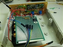
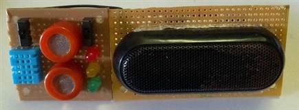
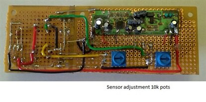
The past two weeks have consisted of parts placement and trying to fit the circuits and boards into a suitable enclosure. I found a 5.3 x 5.3 x 2.0 inch case to use. This is as close as I could get to the approximate TOS tricorder of 8.0 x 6.0 x 2.0 inch enclosure without actually designing and 3D printing one. I would d have liked to have that ability at this point in the project. Even better would have been to print out the actual shape and colors of the original tricorder from the TV series. The photos below show some of the circuitry and components of the Picorder. The main sensory circuit board consists of a temperature/Humidity sensor, an alchol sensor and a CO2 sensor. On the opposite end of this circuit board will be another consisting of a rangefinder sensor and flame detector and possibly an IR motion detector. Software/script development is ongoing.


Although I do own one of the $60.00 TOS tricorder, I could not bring myself to tear it down to try to use it for the contest, nor did I feel it would be suitable to house the components of the RPI, power supply, and sensors.
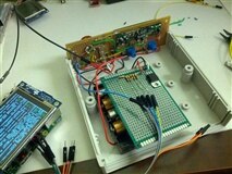
I added another gallery of current photos for the recent progress. Up until this point, I have been using the Pi Model B for the design and testing of each of the stages of development.The sound tests, the temperature and humidity and the flame detection tests have all been done with the Model B. However, in order to continue with my desire to utilize the 3.2 tft display for GUI or graphing the results of the sensor readings in real time, I realized I could not use the same GPIO I/O pins that I used in the sensor tests. Since the displays header uses some of the pins and the header itself prohibits access to the rest, I have had to replace the model B with the Model B+. This allows the use of the GPIO pins from header pins # 27 through 40 to use for the sensory inputs.
As of this date, I have begun to reassign pins and modify all of the software to reference the new assignments throughout the routines as I develop them into a single running script. This step is already proving to be very challenging for a newcomer to programming, especially with the many different ones available each with their own specific syntax requirements.
This next time period will consist of completing of the the enclosure and all remaining components and necessary wiring. Final testing of all components as a complete unit and working out any bugs in hardware and software will follow.
Michael
Top Comments