


In my last two blogs I tried to understand which OCR technique I should use for my project. For getting the answer I have done some research using tesseract OCR and ssocr with some sample images. The lesson I learnt from those experiments is tresseract ocr gives better result for normal text and number and ssocr shows better result for any seven segment style display. Most multimeters, weight scales, blood pressure meter, electricity meters shows result in seven segment style fonts. So, I will use ssocr for this type of display and tresseract for others. For experiment purposes I converted the image in black & white form using OpenCV and for getting only the display portion from the image I used Paint. In this blog post I will perform all the preprocessing programmatically using Python, Numpy and OpenCV. Following block diagram shows all the steps applied for extracting text from an image.

All the above steps will be performed in Raspberry Pi using Python. For preprocessing I will use OpenCV extensively. Two OCR engines will be used based on the display type.
Writing Code for Preprocessing
The preprocessing phase involve several task. The ultimate goal of preprocessing is to get a decent result from OCR. For this purpose we are croppin out only the display portion with black text on white background from the actual meter image and then feeding it to the OCR engine.
Step 1: First we will take an image using Pi camera and resize it. Resizing will help us to avoid any problems with bigger resolution images, make sure the display part still remains in the frame after resizing. Gray scaling is common in all image processing steps. This speeds up other following process since we have nothing to do with the color of the image.
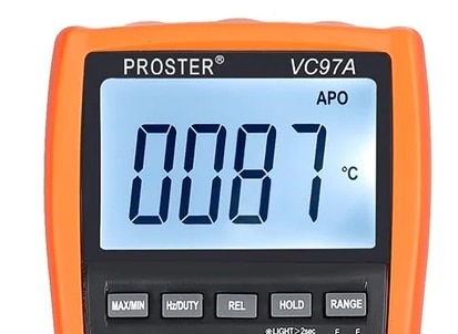
Lets explain the steps with a sample multimeter image. That will help to understand the processing better. Following is the input image we are going to preprocess:
The code for resizing and converting to grayscale is as follows:
image_input = cv2.imread('input_image.jpg')
image_resized = imutils.resize(image_input,height=300)
image_gray = cv2.cvtColor(image_resized, cv2.COLOR_BGR2GRAY)
cv2.imwrite('gray_image.jpg', image_gray)
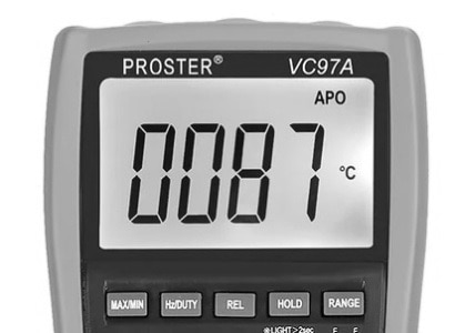
The image would be transformed something like this when this step is done.
Step 2: An image can have useful and useless information, in this case for us only the display text is the useful information the rest are pretty much useless for our program. This useless information is called noise. In this step we will apply bilateral filter in the gray image. Normally using a bilateral filter (Bluring) will remove the unwanted details from an image. The code is:
image_blured = cv2.bilateralFilter(image_gray, 11, 25, 25)
cv2.imwrite('blured_image.jpg', image_gray)
Syntax of applying bilateral filter function is destination_image = cv2.bilateralFilter(source_image, diameter of pixel, sigmaColor, sigmaSpace). You can increase the sigma color and sigma space from 25 to higher values to blur out more background information, but be careful that the useful part does not get blurred. The output image is shown below (no big changed is noticed in this case):

Step 3: The next step is interesting where we perform edge detection. There are many ways to do it, the most easy and popular way is to use the canny edge method from OpenCV. The instruction to do the same is shown below:
image_edged = cv2.Canny(image_blured, 30, 200)
cv2.imwrite('edged_image.jpg', image_edged) #this line is for saving the image
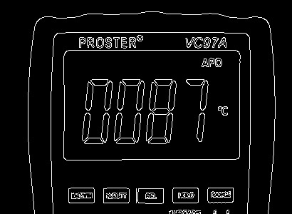
The syntax for edge detection is destination_image = cv2.Canny(source_image, thresholdValue 1, thresholdValue 2). The Threshold Vale 1 and Threshold Value 2 are the minimum and maximum threshold values. Only the edges that have an intensity gradient more than the minimum threshold value and less than the maximum threshold value will be displayed. The resulting image is shown below:
Step 4: Now we will find contours of the display on the image. Contours are the boundaries that define the region of interest in an image. A contour is a collection of points that have been interpolated. The interpolation procedure might be linear, splines, or polynomial, depending on how the curve in the image is described. OpenCV has findContour() function that helps in extracting the contours from the image. We can find all the contours in our edged image using the following code:
contours,hierarchy = cv2.findContours(image_edged, cv2.RETR_TREE, cv2.CHAIN_APPROX_SIMPLE)
contours = imutils.grab_contours(contours)
top_cntrs = sorted(contours, key = cv2.contourArea, reverse = True)[:10]
Once the counters have been detected we sort them from big to small and consider only the first 10 results ignoring the others. In our image the counter could be anything that has a closed surface like buttons, knobs and display but we are interested on only the display contours. To filter the display image among the obtained results, we will loop though all the results and check which has a rectangle shape contour with four sides and closed figure. Since a display would definitely be a rectangle four sided figure.
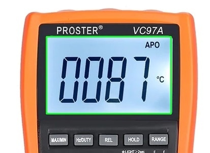
Following image shows the identified contours in the image with green boxes:

The following code snippet was used to identify the display contours among 10 largest contours.
for c in top_cntrs:
    peri = cv2.arcLength(c, True)
    approx = cv2.approxPolyDP(c, 0.04 * peri, True)
    if len(approx) == 4:
        x,y,w,h = cv2.boundingRect(approx)
        cv2.rectangle(image_input,(x,y),(x+w,y+h),(36,255,12),2)
        screen_cnt = approx
        break
The value 0.04 is an experimental value; you can play around it to check which works best for you. Once we have found the right counter we save it in a variable called display_contour and then draw a rectangle box around it to make sure we have detected the display correctly.
Step 5: Now as we know where the display is, the remaining information is pretty much useless for us. So, we will cut out the display from the original image with the help of the display contour. The following code will do this:
def crop_display():
  cntr_pts = screen_cnt.reshape(4,2)
  return cntr_pts


def normalize_contrs(img,cntr_pts):
  ratio = img.shape[0] / 300.0
  norm_pts = np.zeros((4,2), dtype="float32")

  s = cntr_pts.sum(axis=1)
  norm_pts[0] = cntr_pts[np.argmin(s)]
  norm_pts[2] = cntr_pts[np.argmax(s)]

  d = np.diff(cntr_pts,axis=1)
  norm_pts[1] = cntr_pts[np.argmin(d)]
  norm_pts[3] = cntr_pts[np.argmax(d)]

  norm_pts *= ratio

  (top_left, top_right, bottom_right, bottom_left) = norm_pts

  width1 = np.sqrt(((bottom_right[0] - bottom_left[0]) ** 2) + ((bottom_right[1] - bottom_left[1]) ** 2))
  width2 = np.sqrt(((top_right[0] - top_left[0]) ** 2) + ((top_right[1] - top_left[1]) ** 2))
  height1 = np.sqrt(((top_right[0] - bottom_right[0]) ** 2) + ((top_right[1] - bottom_right[1]) ** 2))
  height2 = np.sqrt(((top_left[0] - bottom_left[0]) ** 2) + ((top_left[1] - bottom_left[1]) ** 2))

  max_width = max(int(width1), int(width2))
  max_height = max(int(height1), int(height2))

  dst = np.array([[0,0], [max_width -1, 0],[max_width -1, max_height -1],[0, max_height-1]], dtype="float32")
  persp_matrix = cv2.getPerspectiveTransform(norm_pts,dst)
  return cv2.warpPerspective(img,persp_matrix,(max_width,max_height))
display_image = normalize_contrs(image_input,crop_display())
#display image is now segmented.
gry_disp = cv2.cvtColor(display_image, cv2.COLOR_BGR2GRAY)
gry_disp = exposure.rescale_intensity(gry_disp, out_range= (0,255))

#thresholding
ret, thresh = cv2.threshold(gry_disp,127,255,cv2.THRESH_BINARY)
cv2.imwrite('display.jpg', thresh)
After running the above code the output will be as follows. This is nothing but the display portion we need as the input of the OCR. Normally added to cropping the image, we also make it gray. This is done to improve the character recognition in next step.
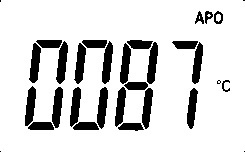
Now, for doing OCR using ssocr use the following code:
import os
os.system("/home/pi/ssocr/ssocr -t -d -1 display.jpg")
You will get maybe 0087 or in some case it can be 0081.
In the command -t is for threshold value which is not specify here, -d is for number of digit and keep it -1 for not limiting the number of digits in the image. To know the details about ssocr and its command please have a look here: https://www.unix-ag.uni-kl.de/~auerswal/ssocr/.
The complete code from taking image from Raspberry Pi Camera to the ORC output is as follows:
import numpy as np
import cv2
import imutils
from skimage import exposure
from pytesseract import image_to_string
import PIL
from picamera import PiCamera
from time import sleep
import os


def take_picture(should_save=False, d_id=0):
  camera = PiCamera()
  camera.start_preview()
  sleep(10) #stabilize camera
  camera.capture('/home/pi/picture.jpg')
  camera.stop_preview()
  img = cv2.imread('/home/pi/picture.jpg')
  return img

def cnvt_edged_image(img_arr, should_save=True):
  # ratio = img_arr.shape[0] / 300.0
  image = imutils.resize(img_arr,height=300)
  gray_image = cv2.bilateralFilter(cv2.cvtColor(image, cv2.COLOR_BGR2GRAY),11, 17, 17)
  edged_image = cv2.Canny(gray_image, 30, 200)

  if should_save:
    cv2.imwrite('/home/pi/cntr_ocr.jpg', edged_image)

  return edged_image

'''image passed in must be ran through the cnv_edge_image first'''
def find_display_contour(edge_img_arr):
  display_contour = None
  edge_copy = edge_img_arr.copy()
  contours,hierarchy = cv2.findContours(edge_copy, cv2.RETR_TREE, cv2.CHAIN_APPROX_SIMPLE)
  top_cntrs = sorted(contours, key = cv2.contourArea, reverse = True)[:10]

  for cntr in top_cntrs:
    peri = cv2.arcLength(cntr,True)
    approx = cv2.approxPolyDP(cntr, 0.02 * peri, True)

    if len(approx) == 4:
      display_contour = approx
      break

  return display_contour

def crop_display(image_arr):
  edge_image = cnvt_edged_image(image_arr)
  display_contour = find_display_contour(edge_image)
  cntr_pts = display_contour.reshape(4,2)
  return cntr_pts


def normalize_contrs(img,cntr_pts):
  ratio = img.shape[0] / 300.0
  norm_pts = np.zeros((4,2), dtype="float32")

  s = cntr_pts.sum(axis=1)
  norm_pts[0] = cntr_pts[np.argmin(s)]
  norm_pts[2] = cntr_pts[np.argmax(s)]

  d = np.diff(cntr_pts,axis=1)
  norm_pts[1] = cntr_pts[np.argmin(d)]
  norm_pts[3] = cntr_pts[np.argmax(d)]

  norm_pts *= ratio

  (top_left, top_right, bottom_right, bottom_left) = norm_pts

  width1 = np.sqrt(((bottom_right[0] - bottom_left[0]) ** 2) + ((bottom_right[1] - bottom_left[1]) ** 2))
  width2 = np.sqrt(((top_right[0] - top_left[0]) ** 2) + ((top_right[1] - top_left[1]) ** 2))
  height1 = np.sqrt(((top_right[0] - bottom_right[0]) ** 2) + ((top_right[1] - bottom_right[1]) ** 2))
  height2 = np.sqrt(((top_left[0] - bottom_left[0]) ** 2) + ((top_left[1] - bottom_left[1]) ** 2))

  max_width = max(int(width1), int(width2))
  max_height = max(int(height1), int(height2))

  dst = np.array([[0,0], [max_width -1, 0],[max_width -1, max_height -1],[0, max_height-1]], dtype="float32")
  persp_matrix = cv2.getPerspectiveTransform(norm_pts,dst)
  return cv2.warpPerspective(img,persp_matrix,(max_width,max_height))

def process_image(orig_image_arr):
  ratio = orig_image_arr.shape[0] / 300.0

  display_image_arr = normalize_contrs(orig_image_arr,crop_display(orig_image_arr))
  #display image is now segmented.
  gry_disp_arr = cv2.cvtColor(display_image_arr, cv2.COLOR_BGR2GRAY)
  gry_disp_arr = exposure.rescale_intensity(gry_disp_arr, out_range= (0,255))

  #thresholding
  ret, thresh = cv2.threshold(gry_disp_arr,127,255,cv2.THRESH_BINARY)
  cv2.imwrite('/home/pi/pros_contour.jpg', thresh)
  return thresh

def ocr_image(orig_image_arr):
  #otsu_thresh_image = PIL.Image.fromarray(process_image(orig_image_arr))
  #return image_to_string(otsu_thresh_image, lang="letsgodigital", config="-psm 100 -c tessedit_char_whitelist=.0123456789")
  return os.system("/home/pi/ssocr/ssocr -t -d -1 /home/pi/pros_contour.jpg")
In my next blog I will add the necessary buttons with the Raspberry Pi to control the operation and add necessary frame to the Raspberry Pi.

