In this blog, I would like to discuss the limited resources available when working with a basic microcontroller like the ATtiny85. I was surprised to find that while communication is straightforward with other boards, it is not as simple when it comes to a Raspberry Pi, especially the Pi 4.
The process of establishing communication was incredibly frustrating. It took several weeks of trying numerous libraries, communication methods, and protocols. Ultimately, I settled on using the I2C protocol due to its straightforward wiring. However, I am fully aware that I chose this protocol because, as a future personal project, I plan to integrate a small OLED display for the GUI, and I would need to communicate using this protocol. It was a headache because losing communication between the Raspberry Pi and the ATtiny was a complex issue to resolve. However, after reading about transmission speeds and synchronization processes, I gained a better understanding. Looking back, I can say that I achieved most of the goals I set, except for creating the PCB, which was the most exciting part for me. I must express my gratitude for the criticisms received in the first blog because, without them, I may have damaged the Raspberry Pi during the initial testing phase.
Now let's talk about the electronic part. The pin connections were straightforward, following the ATtiny85 pinout. However, the ATtiny85 operates at 5V, powered by the circuit regulator, while the Raspberry Pi requires a voltage of 3.3V. This presented a dilemma: whether to use a voltage divider or a level shifter. Using a voltage divider was not an option because an incorrect voltage level could be interpreted as a communication failure, leading to misinterpretation by the ATtiny85 and potentially causing serious issues. Therefore, a level shifter was the solution.
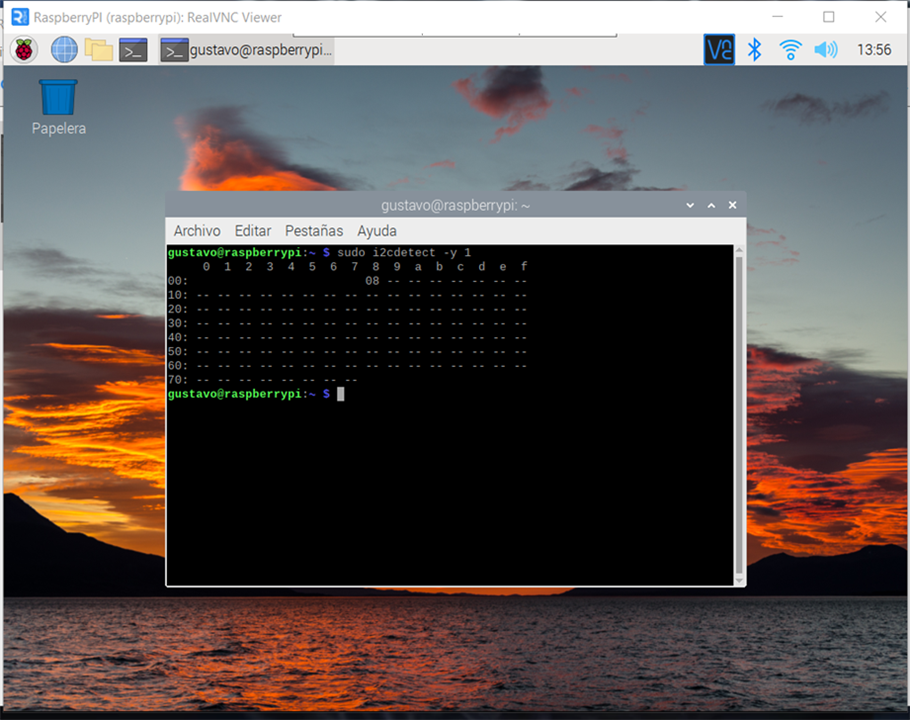
One side handles the "high" voltages, while the other side handles the "low" voltages, ensuring safety and eliminating any potential danger. Once everything was wired up, I embarked on the journey of establishing communication and understanding their interactions. I tried various I2C library codes, including TinyWire.h, TinyWire.S, and WireAT.h, but I couldn't achieve successful data transmission. The Raspberry Pi recognized the ATtiny as a component, but I struggled to find a way to make the ATtiny act as a slave in communication. It only seemed capable of sending data, which was promising for future steps involving OLED displays, but not for the immediate project. However, I knew I was on the right track when I at least managed to establish proper addressing.
Here are some codes that work for the Attiny and maybe to communicate to other devices but no with the rasp
Maybe this blog should be named HOW NOT TO ESTABLISH AN I2C COMMUNICATION
#include <TinyWireM.h>

#define SLAVE_ADDRESS 0x10

void setup() {
  TinyWireM.begin();
}

void loop() {
  // Envía un byte de datos desde el ATtiny85
  TinyWireM.beginTransmission(SLAVE_ADDRESS);
  TinyWireM.write(0x42); // Envía el valor 0x42
  TinyWireM.endTransmission();

  delay(1000);
}
I tied sending characters, numbers strings with no success. When I was almost giving up I found a library that comes with a "Core" board which was created in 2006 I thought it might not work and is old enough to keep on failing with my project. But what a surprise:

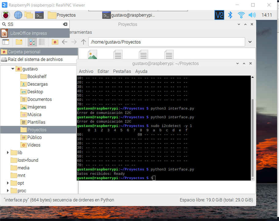
I was sending the string Ready as you can see in the terminal I got it then I started testing with a basic GUI to keep tracking the behavior of the i2c communication.
import smbus

# Dirección del esclavo I2C (ATtiny85)
SLAVE_ADDRESS = 8

# Inicializar el bus I2C
bus = smbus.SMBus(1)

# Leer los datos enviados por el ATtiny85
def read_data():
    try:
        # Leer hasta 6 bytes de datos desde el esclavo
        data = bus.read_i2c_block_data(SLAVE_ADDRESS, 0, 6)
        # Convertir los bytes en una cadena
        message = ''.join(chr(byte) for byte in data)
        return message
    except IOError:
        print("Error de comunicación I2C")
        return None

# Leer y mostrar los datos enviados por el ATtiny85
received_data = read_data()
if received_data is not None:
    print("Datos recibidos:", received_data)
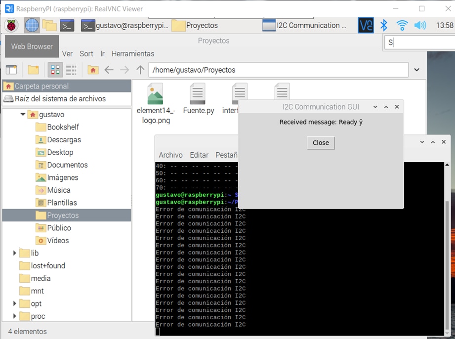
And later with a GUI because the connection was broken after a few minutes and I had to see it to see what was happening.

import smbus
import tkinter as tk

SLAVE_ADDRESS = 8
I2C_BUS = 1
BAUD_RATE = 9600

bus = smbus.SMBus(I2C_BUS)

def read_data():
    try:
        data = bus.read_i2c_block_data(SLAVE_ADDRESS, 0, 7)
        message = ''.join(chr(byte) for byte in data)
        return message
    except IOError:
        print("Error de comunicación I2C")
        return None

def update_message_and_duration():
    received_data = read_data()
    if received_data is not None:
        message_label.config(text="Received message: " + received_data)

    root.after(1000, update_message_and_duration)

root = tk.Tk()
root.title("I2C Communication GUI")

message_label = tk.Label(root, text="Received message: ")
message_label.pack(pady=10)

update_message_and_duration()

close_button = tk.Button(root, text="Close", command=root.quit)
close_button.pack(pady=10)

root.mainloop()
Later I understand that speed was not appropriate and that the connection was falling because of a mismatch in synchronization. And at this point, everything is almost done. I'm very happy because the established objectives were done. In the next Blog, I'll share the GUI it will be a little one but I had to share this with you how not to establish an i2c communication.
