


This will be a rather short blog post. In the previous one, I briefly discussed the challenges of communication. I also read a very insightful comment that I will take into account for future projects where I need to observe the behavior of microcontroller communication. Now, the only thing left is to show you the small graphical interface. It's not complex, as its purpose is to be user-friendly and achieve the initial objective: to be an easy-to-make, use, and simple source for those who want to enter the world of electronics.
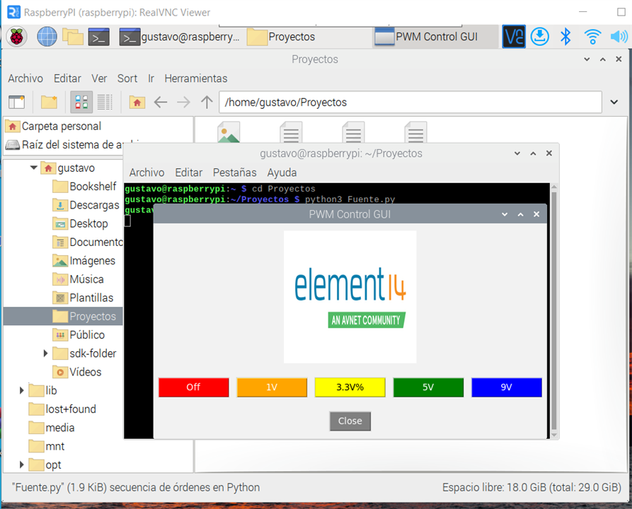
In the attached code you can see the communication process and how it is being read on the other side by the Attiny85.
import smbus
import tkinter as tk
from PIL import ImageTk, Image

SLAVE_ADDRESS = 8
I2C_BUS = 1
BAUD_RATE = 9600

bus = smbus.SMBus(I2C_BUS)

def send_command(command):
    bus.write_byte(SLAVE_ADDRESS, ord(command))

def control_pwm(value):
    if value == 0:
        send_command('0')
    elif value == 25:
        send_command('1')
    elif value == 50:
        send_command('2')
    elif value == 75:
        send_command('3')
    elif value == 100:
        send_command('4')

def create_pwm_control_buttons():
    button_frame = tk.Frame(root, bg="#F2F2F2")
    button_frame.pack(pady=10)

    off_button = tk.Button(button_frame, text="Off", width=10, command=lambda: control_pwm(0), bg="#FF0000", fg="white")
    off_button.grid(row=0, column=0, padx=5)

    pwm25_button = tk.Button(button_frame, text="1V", width=10, command=lambda: control_pwm(25), bg="#FFA500", fg="white")
    pwm25_button.grid(row=0, column=1, padx=5)

    pwm50_button = tk.Button(button_frame, text="3.3V%", width=10, command=lambda: control_pwm(50), bg="#FFFF00", fg="black")
    pwm50_button.grid(row=0, column=2, padx=5)

    pwm75_button = tk.Button(button_frame, text="5V", width=10, command=lambda: control_pwm(75), bg="#008000", fg="white")
    pwm75_button.grid(row=0, column=3, padx=5)

    pwm100_button = tk.Button(button_frame, text="9V", width=10, command=lambda: control_pwm(100), bg="#0000FF", fg="white")
    pwm100_button.grid(row=0, column=4, padx=5)

root = tk.Tk()
root.title("PWM Control GUI")
root.configure(bg="#F2F2F2")

# Element14 Logo
image_path = "element14_logo.png"
element14_logo = Image.open(image_path)
element14_logo = element14_logo.resize((200, 200), Image.ANTIALIAS)
element14_logo = ImageTk.PhotoImage(element14_logo)

logo_label = tk.Label(root, image=element14_logo, bg="#F2F2F2")
logo_label.pack(pady=10)

create_pwm_control_buttons()

close_button = tk.Button(root, text="Close", command=root.quit, bg="#808080", fg="white")
close_button.pack(pady=10)

root.mainloop()
#include <Wire.h>

#define SLAVE_ADDRESS 8
#define PWM_FREQ 1000

int pwmValue = 0;

void setup() {
  pinMode(6, OUTPUT);                 // Configura el pin 6 como salida para el PWM
  analogWrite(6, pwmValue);           // Inicializa el PWM en 0
  Wire.begin(SLAVE_ADDRESS);          // Inicia el bus I2C con la dirección del esclavo
  Wire.onReceive(receiveEvent);       // Registra el evento de recepción de datos

  // Configura la frecuencia del PWM en 1kHz
  TCCR1 = TCCR1 & 0xE7 | 0x03;        // Fija el prescaler en 64
  OCR1A = 249;                        // Establece el valor de comparación para 1kHz
  TCCR1 |= (1 << CTC1);               // Habilita la operación en modo CTC
  TIMSK |= (1 << OCIE1A);             // Habilita la interrupción del timer 1 para el modo CTC
}

void loop() {
  // No se requiere código adicional en el loop para el control del PWM
}

void receiveEvent(int numBytes) {
  while (Wire.available()) {
    char command = Wire.read();       // Lee el comando recibido desde el maestro

    switch (command) {
      case '0':
        pwmValue = 0;                  // Establece el PWM en 0 (apagado)
        break;
      case '1':
        pwmValue = 64;                 // Establece el PWM en 25% del ciclo de trabajo
        break;
      case '2':
        pwmValue = 102;                // Establece el PWM en 40% del ciclo de trabajo
        break;
      case '3':
        pwmValue = 179;                // Establece el PWM en 70% del ciclo de trabajo
        break;
      case '4':
        pwmValue = 230;                // Establece el PWM en 90% del ciclo de trabajo
        break;
    }

    analogWrite(6, pwmValue);         // Actualiza el valor del PWM en el pin 6
  }
}
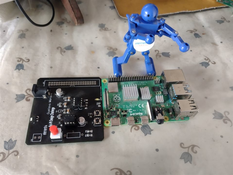
Throughout the blogs, I've presented diagrams, physical tests, and finally, the achieved communication. I know it may not be something complex, but it can be useful to many people, especially the target audience consisting of beginners. As a personal project, I will seek a way to manufacture it on a PCB that can easily fit into a breadboard, directly controllable from the board. Of course, the challenge was to do something with the Raspberry Pi, and my contribution was communication and interface with a less sophisticated microcontroller. As a personal endeavor, I will work on creating a low-cost source that fits into the breadboard.
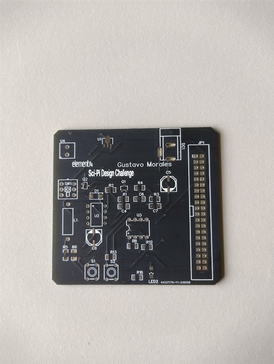
As I said on my very first blog I though I could make a PCB by myself however some mistakes were made during the process but I want to share with you what the first PCB looked like. And I did not make it once again as I said on my second blog because the shipping process for the first PCB took around 3 weeks.
| {gallery}PCB |
|---|
|
|
|
|
 |

I've learned a lot on this journey with the project, and I have nothing left but to express my gratitude for your participation.
