I really appreciated some comments made on my previous blog, which were very constructive, I started this project not from the beginning but now being aware of what can now happen if connecting directly with the rasp. The first steps were looking for some replacements if needed and choosing another microcontroller in order to approach some safety measurements. For this purpose the first thing to add was a micro, for this time I said an Attiny85 I know I could use a powerful micro such as a raspberry pico to keep whit this challenge however the main idea is to have a cheap solution. Supports the idea that this is made to help future enthusiasts that will not buy as expensive power supplies as there are outside at the market and of course, this can be part of the firs projects done by everyone since they can purchase the PCBs by using some files I am providing.
Ok let's start talking about Mosfets I used the P channel and researched the suggestion of using N channel ones, they are almost the same working for one or another, one of the main reasons I used P channels is because there are not available many mosfets in local warehouses so I had to stay to what I can have. 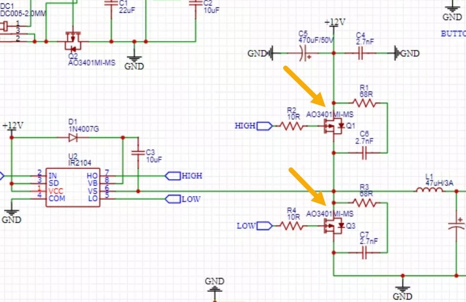
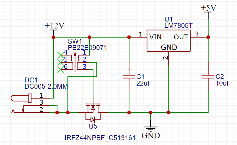
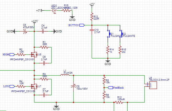
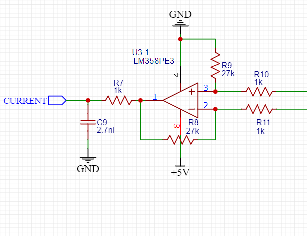
This was one of the main questions, and you were almost right in one thing is that I did not consider about power engaged here and that was not the best idea to use that transistor instead I am using then an IRF44NPBF, I know that the encapsulation is even bigger and not SMD, I know I could find another one but there is just small time to bring parts from US or China to my country remember the time I said that I send to the factory to get my pcbs the original ones with all those mistakes have not arrived even and there had been about 3 weeks supposing I can have them here in 3 more weeks I'll be out of date so most of my circuit was changed in order to use THT components so at least I can prove it on a breadboard to have some results than by my own I'll make mines with SMD to reduce space. Later and maybe adapt it to fit in a breadboard as common ones are attached but with the plus that it can vary the voltage. Another thing that I did not change was the opamp and the feedback the opamp is going to test the voltage drop in that specific point and the code will be calculated to approximate the current I know that there is a voltage drop that will not give the 5V exactly for example but with a minimum drop that may not affect those projects to start with.
| {gallery}My Gallery Title |
|---|
 |
 |
 |
 |
The Attiny85 Variable Power Supply is an advanced, digitally-controlled power supply circuit featuring microcontroller-based control and real-time feedback. The primary goal of this design is to enable precise regulation of the output voltage through pulse-width modulation (PWM) generated by the Attiny85 microcontroller. This power supply system is ideal for a wide range of applications, including research, education, and industrial settings, where adjustable, stable, and precise voltage sources are required.
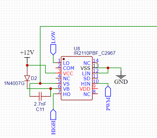
The heart of this design is the Attiny85 microcontroller, programmed to generate the PWM signal that controls the output voltage. The microcontroller interfaces with the IR2104 gate driver, which drives the switching regulator with the aid of an IRFZ44N MOSFET. This topology enables efficient power conversion and voltage regulation while providing precise control over the output voltage.
User interaction with the system is achieved through pushbuttons, whose voltage levels change upon activation. The Attiny85 monitors these voltage drops and infers which button has been pressed. Users may employ these pushbuttons to modify the output voltage or engage other feature settings.
For real-time interaction and feedback, this design incorporates an I2C interface that connects to a Raspberry Pi or similar microprocessors. A level shifter is used to adapt the voltage levels from the Attiny85 to the Raspberry Pi safely. The Raspberry Pi can then display pertinent information, such as voltage levels and system status, on a screen or collect data for further analysis.
By providing a sophisticated, robust, variable power supply with real-time interaction capabilities, this project is highly beneficial for an academic community, as it allows students, researchers, and professionals alike to explore, manipulate, and analyze various electronic systems directly. Furthermore, it offers the possibility of customizing the hardware and software components to cater to the unique needs of specific projects.
I will attach the code on the next blog just to explain more and leave the last thing in the communication but thanks to your comments, pointing voltage maximums lead me to look for level shifters as I mentioned before that will help in the communication process Thanks to all!

-

soldering.on
-
Cancel
-
Vote Up
0
Vote Down
-
-
Sign in to reply
-
More
-
Cancel
Comment-

soldering.on
-
Cancel
-
Vote Up
0
Vote Down
-
-
Sign in to reply
-
More
-
Cancel
Children