element14 Community
element14 Community
    Register Log In
  • Site
  • Search
  • Log In Register
  • Community Hub
    Community Hub
    • What's New on element14
    • Feedback and Support
    • Benefits of Membership
    • Personal Blogs
    • Members Area
    • Achievement Levels
  • Learn
    Learn
    • Ask an Expert
    • eBooks
    • element14 presents
    • Learning Center
    • Tech Spotlight
    • STEM Academy
    • Webinars, Training and Events
    • Learning Groups
  • Technologies
    Technologies
    • 3D Printing
    • FPGA
    • Industrial Automation
    • Internet of Things
    • Power & Energy
    • Sensors
    • Technology Groups
  • Challenges & Projects
    Challenges & Projects
    • Design Challenges
    • element14 presents Projects
    • Project14
    • Arduino Projects
    • Raspberry Pi Projects
    • Project Groups
  • Products
    Products
    • Arduino
    • Avnet Boards Community
    • Dev Tools
    • Manufacturers
    • Multicomp Pro
    • Product Groups
    • Raspberry Pi
    • RoadTests & Reviews
  • About Us
  • Store
    Store
    • Visit Your Store
    • Choose another store...
      • Europe
      •  Austria (German)
      •  Belgium (Dutch, French)
      •  Bulgaria (Bulgarian)
      •  Czech Republic (Czech)
      •  Denmark (Danish)
      •  Estonia (Estonian)
      •  Finland (Finnish)
      •  France (French)
      •  Germany (German)
      •  Hungary (Hungarian)
      •  Ireland
      •  Israel
      •  Italy (Italian)
      •  Latvia (Latvian)
      •  
      •  Lithuania (Lithuanian)
      •  Netherlands (Dutch)
      •  Norway (Norwegian)
      •  Poland (Polish)
      •  Portugal (Portuguese)
      •  Romania (Romanian)
      •  Russia (Russian)
      •  Slovakia (Slovak)
      •  Slovenia (Slovenian)
      •  Spain (Spanish)
      •  Sweden (Swedish)
      •  Switzerland(German, French)
      •  Turkey (Turkish)
      •  United Kingdom
      • Asia Pacific
      •  Australia
      •  China
      •  Hong Kong
      •  India
      •  Korea (Korean)
      •  Malaysia
      •  New Zealand
      •  Philippines
      •  Singapore
      •  Taiwan
      •  Thailand (Thai)
      • Americas
      •  Brazil (Portuguese)
      •  Canada
      •  Mexico (Spanish)
      •  United States
      Can't find the country/region you're looking for? Visit our export site or find a local distributor.
  • Translate
  • Profile
  • Settings
Sci-Pi Design Challenge
  • Challenges & Projects
  • Design Challenges
  • Sci-Pi Design Challenge
  • More
  • Cancel
Sci-Pi Design Challenge
Blog Making modules to create Voltage power Supply based on Rasberry Blog #2
  • Blog
  • Forum
  • Documents
  • Leaderboard
  • Polls
  • Files
  • Members
  • Mentions
  • Sub-Groups
  • Tags
  • More
  • Cancel
  • New
Join Sci-Pi Design Challenge to participate - click to join for free!
  • Share
  • More
  • Cancel
Group Actions
  • Group RSS
  • More
  • Cancel
Engagement
  • Author Author: GustavoMorales
  • Date Created: 5 Jun 2023 2:24 PM Date Created
  • Views 655 views
  • Likes 12 likes
  • Comments 5 comments
  • Design
  • raspberry pi
Related
Recommended

Making modules to create Voltage power Supply based on Rasberry Blog #2

GustavoMorales
GustavoMorales
5 Jun 2023

In my previous blog post, I briefly introduced the concept of utilizing Raspberry Pi as a central control board for various modules. Today, I'd like to delve deeper into one of the fundamental aspects of this idea: the voltage power supply. By harnessing the power of Pulse Width Modulation (PWM) signals and employing a half H bridge, we can effectively manage the frequency and transmit data to other components within the system.

However, it's important to note that this project aims to go beyond mere programming; it involves the creation of a comprehensive electronic device. To give you a better understanding of my design, let me present the schematic diagram.

image

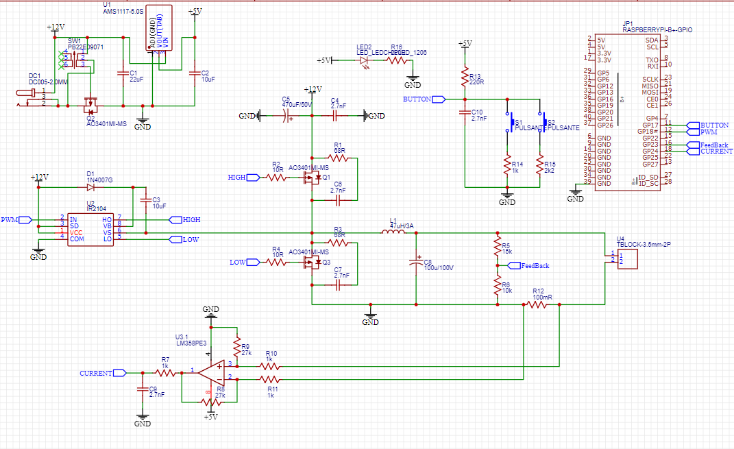
The schematic diagram serves as a visual representation of the connections and interactions between the various components in our electronic device. It outlines the arrangement of key elements such as the Raspberry Pi, voltage power supply circuit, PWM signals, and the half H bridge module.

At the core of the system, the Raspberry Pi acts as the main control unit, providing the necessary computational power and connectivity. It generates PWM signals to regulate the voltage supply and communicate with the other modules effectively.

To ensure a stable and reliable power source, we incorporate a voltage power supply circuit. This circuit is responsible for converting the input voltage to the desired level required by the components. It also serves as a protective measure, preventing voltage spikes or drops that could potentially damage the connected modules.

By utilizing PWM signals, we can modulate the voltage supply frequency to transmit data to different components within our electronic device. This enables seamless communication between modules and facilitates the smooth operation of the entire system.

To achieve this, we employ a half H bridge module. This module allows bidirectional control of the current flow, enabling us to control the voltage polarity and thus regulate the power supplied to specific components. It acts as a switch, directing the flow of current as required by the system.

Overall, this schematic represents the initial groundwork for our electronic device project. It showcases how the Raspberry Pi, voltage power supply circuit, PWM signals, and the half H bridge module come together to create a robust and versatile system. In future blog posts, I will expand upon other modules and functionalities, demonstrating the full potential of this project.

Let's explain more from the circuit.

image

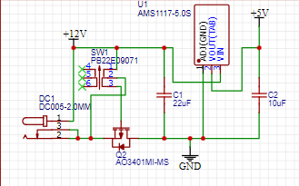
In the schematic diagram, we have included a 5V regulator configuration. This configuration begins with a transistor-based protection mechanism, which safeguards against overcurrent and reversed current situations. By incorporating this protection, we can prevent any potential damage to the connected components.

The purpose of the regulator is to ensure a stable 5V power supply, which is essential for the proper functioning of certain components within the system. By supplying a consistent voltage, we can guarantee the reliability and optimal performance of these components.

Additionally, the regulator serves another crucial function by accommodating other voltage inputs. In situations where alternative voltage sources are present, the regulator can handle the necessary adjustments to provide the appropriate voltage level required by the components. This flexibility ensures compatibility with various modules that may have different voltage requirements.

By incorporating this 5V regulator into our design, we can confidently power additional components, knowing that they will receive the necessary voltage for their operation. Furthermore, its ability to handle different voltage inputs adds versatility to our system, allowing us to incorporate diverse modules seamlessly.


image

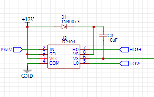
At this point of the circuit, we are making that half h bridge to handle a signal provided by the rasp to operate the voltage when we send some dutty cycle that later will be programmed the IR2104PBF to send the voltage to the rest of the circuits that act as a buck down converter, to keep in mind we can not get higher voltage than provided by the power supply since the configuration is a buck down.

 image

In the circuit diagram, we have reached the final stages of the design. At this point, we introduce the IR2104PBF, which plays a crucial role in processing signals within our system. These signals, provided by the IR2104PBF, are then fed into our Raspberry Pi, effectively enabling a PID (Proportional-Integral-Derivative) control mechanism.

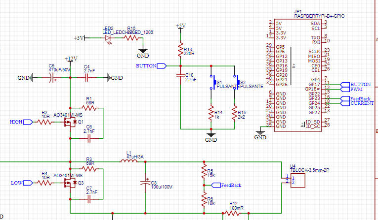
To provide user interaction and control, we have incorporated pushbuttons into our system. These pushbuttons are programmatically configured in our code, allowing users to select predefined voltage levels and perform other specified functions.

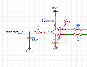
Furthermore, we have included a current measuring component in our circuit. This component utilizes a 100mohm resistor to sense the current passing through the system. The voltage generated across this resistor is then compared using an op-amp, and the resulting voltage is sent to the Raspberry Pi for further mathematical analysis. This current sensing functionality is crucial for monitoring and analyzing the performance of our circuits.

In order to facilitate testing and future expansion, we have provided the option to utilize additional pins on the Raspberry Pi. This allows us to control the power supply without interfering with the necessary pins for other functionalities. By ensuring flexibility in pin usage, we can continue working with the program and exploring new possibilities without constraints.

As we move forward with our project, we will proceed to test our circuits using the current sensor. This will provide valuable data and insights, allowing us to refine and improve the performance of our power supply.

By incorporating the IR2104PBF, pushbuttons, current sensing, and flexible pin usage, we have developed a comprehensive circuit design that showcases the potential of our electronic device. Through continuous development and iteration, we aim to create a robust and versatile power supply system.


image


In my upcoming blog post, I will be introducing another module that I believe is crucial for anyone learning electronics. This module holds significant importance throughout the learning process, and reflecting on my own journey, I wish I had access to this valuable resource from the beginning. I am excited to share my insights and experiences with you in the upcoming post.

Learning electronics can be an exhilarating yet challenging endeavor, requiring a solid foundation and continuous exploration. Throughout my own journey, I have encountered various modules and components that have played a pivotal role in my understanding of electronics.
Thank you for joining me on this journey, and I look forward to sharing this insightful blog post with you soon. Stay tuned for more updates and happy exploring!


  • Sign in to reply

Top Comments

  • shabaz
    shabaz over 2 years ago +1
    Hi, For the MOSFETs, the schematic shows P-ch (indicated with the yellow arrows below), but I think they need to be N-ch: What do these buttons S1 and S2 do? They are connected to a single GPIO,…
  • GustavoMorales
    GustavoMorales over 2 years ago

    Awesome I was thinking during these days about your feedback, I would have had all of this before in order to change everything on my board I made it to the PCB manufacturers (don't want to say names to avoid problems) I am thinking on everything that was said about changing transistors and all stuff necessary to work at this point I am kind of concerned on how to fix everything on time, maybe as Michaelkellet said considering on making some extra effort using another controller to work on the analog part, I did not consider the missing ADC and that was a really big mistake I am now working on another schematic that works with an analog controller changing mosfets and keeping in mid voltage that can be tolerated by the rasp and finally making a user interface with the rasp.

    As I said I really wanted to have some physically made on time and my PCB I ordered about 3 weeks ago has not arrived and if I change everything now it will be late at the end. Maybe what I can do is simulate in any software to check the status and at least present the user interface since there is not enough time to get new PCBs on time. And another thing is that some THT components are not sold in my country so I can try it on a breadboard that is another challenging thing I will do my best to present something that can be done in the future and keep on working with everybody help 

    • Cancel
    • Vote Up 0 Vote Down
    • Sign in to reply
    • More
    • Cancel
  • michaelkellett
    michaelkellett over 2 years ago

    I see you have already had some good feedback about this design.

    The Raspberry Pi is just the wrong type of controller for  power supply.

    Power supply control is usually described as a "Hard Real Time" software problem, which means that not only the values of the computed outputs are significant but that they must be ready in a specified time interval (Real Time) and the interval is short compared with the operating system (if any) latency. The Pi (as a Linux computer) just doesn't work well in this space.

    There are many micro controllers with peripherals designed for this type of application. They have fast ADCs, PWM timers with emergency stop and programmable dead time and other useful features. They are cheap and available on dev boards which are easy to use (eg ST Nucleo boards.)

    A much more satisfactory system architecture would be to use the Pi for user interface and high level stuff, talking to the micro controlling the power supply via UART, SPI or I2C.

    You may be wondering why the control loop needs to be fast - consider the situation where your load is drawing a large current, the feedback loop will adjust the PWM to compensate for the losses in the components due to that current. If the load suddenly reduces its demand the PWM must respond very quickly (within a small number of switching cycles) to change the PW or the output voltage will rise to possibly destructive voltages.

    MK

    • Cancel
    • Vote Up 0 Vote Down
    • Sign in to reply
    • More
    • Cancel
  • shabaz
    shabaz over 2 years ago in reply to jc2048

    Hi Jon,

    Good points. Also I just noticed the MOSFET at the DC input has a floating gate when the switch SW1 is in the upward position on the schematic. 

    The resistor R13 (connected to the two buttons) should be connected to 3.3V, not 5V.

    • Cancel
    • Vote Up 0 Vote Down
    • Sign in to reply
    • More
    • Cancel
  • jc2048
    jc2048 over 2 years ago in reply to shabaz

    Useful design review.

    The p-channel device substitution affects the power input 'perfect diode' as well.

    Not sure two snubbers on the half-bridge switching node is really necessary either, but components can be left off the board, so not of any real consequence.

    Personally, I wouldn't feel very confident trying to do real-time control systems stuff like this with an SBC like a Raspberry Pi. I think I'd look to either an analogue controller, with the Pi manipulating the feedback for the control, or a small microcontroller of the kind designed for power control, which the Pi could talk to.

    • Cancel
    • Vote Up 0 Vote Down
    • Sign in to reply
    • More
    • Cancel
  • shabaz
    shabaz over 2 years ago

    Hi,

    For the MOSFETs, the schematic shows P-ch (indicated with the yellow arrows below), but I think they need to be N-ch:

    image

    What do these buttons S1 and S2 do? They are connected to a single GPIO, is that intentional, or should they be going to separate GPIO? The single GPIO could distinguish the different buttons if it were configured as an analog input, but I don't know if there are any ADC on the Pi. 

    image

    For the FeedBack resistors R5 and R6, with the values in the schematic, the output will be 5V, but the Pi can only accept 3.3V maximum, so those resistor values need modifying. However, is there a reason such feedback is needed, and from this point in the circuit?

    image

    I also didn't understand the current sensing circuit. The output goes directly to the Pi, but the Pi doesn't have an ADC:

    image

    • Cancel
    • Vote Up +1 Vote Down
    • Sign in to reply
    • More
    • Cancel
element14 Community

element14 is the first online community specifically for engineers. Connect with your peers and get expert answers to your questions.

  • Members
  • Learn
  • Technologies
  • Challenges & Projects
  • Products
  • Store
  • About Us
  • Feedback & Support
  • FAQs
  • Terms of Use
  • Privacy Policy
  • Legal and Copyright Notices
  • Sitemap
  • Cookies

An Avnet Company © 2025 Premier Farnell Limited. All Rights Reserved.

Premier Farnell Ltd, registered in England and Wales (no 00876412), registered office: Farnell House, Forge Lane, Leeds LS12 2NE.

ICP 备案号 10220084.

Follow element14

  • X
  • Facebook
  • linkedin
  • YouTube