Pollinator Pollster (Powered by Pi)
Welcome to the third blog post of this project. In the last week, all components for the first prototype have arrived (yay!), I’ve been able to bench-test the power components and radios, and there has been progress on the Pi 4 hub which will run the web server used to share the sensor data.
Update Video
Project Plan
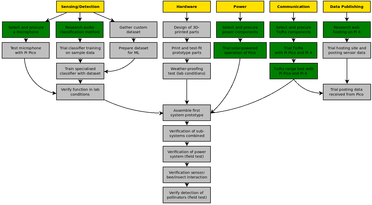
Some more boxes coloured green this time, in the 'Power' and 'Communication' streams. The two main remaining activities are the mechanical design and creation of the 3D printed parts, and also the machine learning aspects of this project - the ML is not something I have focussed on recently as I wanted to get all of the hardware aspects out of the way first in order to be able to focus solely on the ML afterwards (no, I promise this isn't procrastination...).
Radio Programming and Testing
As discussed in the previous project blog, I'd chosen to use the HC-12 transceiver to send data back to the Pi 4 hub from the Pi Pico sensors. Getting this to work and testing the limits of range was a priority, and I am happy to say is now complete. Here are some details of the process.
Firstly, it is necessary to program the HC-12, which has its own microcontroller and internal memory (so programmed settings are retained after power off, or when connected to a different device). This is done using 'AT' commands over serial. I chose to use an Arduino MEGA to program mine, as I am more experienced with Arduino and the Arduino IDE. This particular blog is great background reading on HC-12 use and programming. To put the HC-12 in programming mode, when connected to the Arduino before power-on, connect the 'SET' pin on the HC-12 to GND on the Arduino. After plugging the Arduino into your PC and opening the editor, upload the following code to the Arduino.
#include <SoftwareSerial.h>
SoftwareSerial hc12(10, 11);

void setup() {
  Serial.begin(9600);
  hc12.begin(9600);
  Serial.println("Let's Start!");
}

void loop() {
  if (hc12.available()) {
    Serial.write(hc12.read());
  }
  if (Serial.available()) {
    hc12.write(Serial.read());
  }
}
Open the Serial Monitor, set baud rate to 9600, and send the command 'AT+RX', to which the HC-12 should respond with a list of the default programmed settings. You need to overwrite those by sending the following commands 'AT+C1', 'AT+P4', and 'AT+FU4'. This sets the HC-12 to channel 1 (433.4MHz), power level 4 (8 dBm, below the UK limit), and 'Mode 4' which is the long range mode which functions at a baud rate of 1200. Repeat for both of the transceiver pair, not forgetting to check your local radio regulations to choose a frequency and power level which is compliant.
Now at this stage we can connect the HC-12 to the Pico. Pins: HC12 VCC -> Pico 3.3V Pin, HC12 GND -> Pico GND Pin, HC-12 RXD -> Pico GP4 Pin, HC-12 TXD -> Pico GP5 Pin.
Save the below code to the Pico as main.py so that it will run immediatly when the Pico is powered. Thanks to this forum post which gave me a big help on getting the program together.
#sender code:
from machine import UART, Pin
import utime
led_onboard = machine.Pin(25, machine.Pin.OUT)
uart = UART(1, 1200, rx=Pin(5), tx=Pin(4) , bits=8, parity=None, stop=1, timeout=1)
print(uart)
i = 1
while True:
    led_onboard.value(1)
    msg = 'No. ' + str(i)
    uart.write(msg)
    utime.sleep(1)
    led_onboard.value(0)
    utime.sleep(9)
    i = i + 1
Next up let's get the other HC-12 attached to the Raspberry Pi and set up. I used my Pi 3B as the new Pi 4 was busy with the web server work and I didn't want to disrupt that. The pins are: HC12 VCC -> Pi Pin 4, HC12 GND -> Pi Pin 6, HC-12 RXD -> Pi Pin 10, HC-12 TXD -> Pi Pin 8.
Open the following code in the Thonny editor.
import time
import serial

ser = serial.Serial(
    port='/dev/ttyS0',
    baudrate = 1200,
    parity=serial.PARITY_NONE,
    stopbits=serial.STOPBITS_ONE,
    bytesize=serial.EIGHTBITS,
    timeout=1
)

while 1:
    x=ser.readline()
    print (x)
Now what the Pico code does is every 10 seconds it sends a number to the Pi, increasing in intervals of 1. Those messages will appear in the Serial Monitor in Thonny if everything is working well. My next step was to take quite a few steps down the road, with the Pi 3B and the receiver perched on a windowsill, and the transmitter powered by battery in a small box in my hand. With help, the output on Thonny on the Pi was observed and my position relative to the receiver was measured in Google Earth in order to see the point at which the signal ran out.
Surprisingly, this occured at 280m, so quite a good result all in all and more than necessary for allowing several of the pollinator sensors to be remotely scattered through a habitat, while still remaining in communication with the Pi 4 hub. You can see some video of the test in the project update video at the top of this post.
I Have the Power!
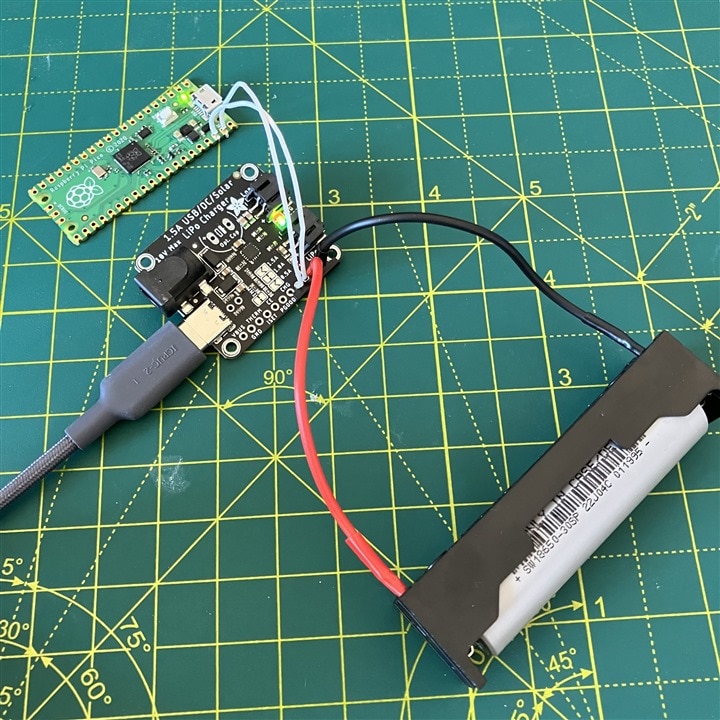
One of the first components to arrive in the post was this little Adafruit Solar Charger. This serves the crucial function within the sensor of interfacing to the solar panel, managing safe charging and discharging of the Lithium 18650 battery, and providing a stable voltage to the Pi Pico and circuitry. Like all Adafruit products there is very thorough documentation online, so it was a breeze to get it soldered to the battery holder and to the Pi Pico.
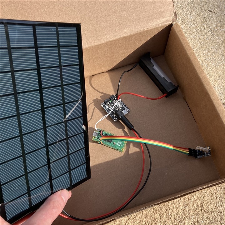
Now the solar panel has arrived (and survived the drop to the hard floor through my letterbox which made a worrying sound!), I've been able to get the whole sensor power system together. Bar the microphone, this is therefore the whole electrical system of the sensor. Here’s a pic of the testing below, and don’t forget when working with Lithium batteries always check and triple-check for shorts, and for correct polarity! Happily there has been a small heatwave here in the UK so there’s tonnes of sun at present to test the solar panel.
| {gallery}Power System |
|---|
|
Adafruit bq24074: Solar charger with Pico and battery. |
|
It works!: 6V solar panel connected and charging the battery. |
Raspberry Pi 4-hosted Website
To share the data collected from the sensors, I have chosen to use a Raspberry Pi 4 as a hub. Using the HC-12 transceivers, it will receive data from any number of identical sensors which may be scattered throughout the nearby habitat.
To maximise the value of this system as a research tool, and also to be able to involve you in the project too, I would like to have the Pi 4 automatically post the incoming sensor data live to a publicly-accessible website, and so to that aim I have been learning how to host a small site on the Pi. This has been a very time consuming exercise as usage of the Pi in this manner is completely new to me, and I am also new to html. Luckily, as with everything Raspberry Pi, there is a huge array of online blogs, tutorials, and resources to help you do this. I had a few dead-ends, perhaps some guides were out-of-date or had errors, but I did find some really great sources, which I’ll share below in case you want to learn to do this to.
- This short blog is a great intro to using Flask and get you exciting results quickly. This was a good first step for me to learn the fundamentals.
- Following that, this much longer blog is a very detailed guide to using Flask with NGINX to build a server on the Pi. There are a few small errors, mainly you need to double-check file paths in the sample code align with what you have on your Pi, but it’s a very thorough overview that was super helpful to get me going.
- Lastly, to learn how to begin adding extra pages, and some simple html formatting, I’d recommend this tutorial.
I bought a web domain and set up a free Cloudflare account to link the Pi server to the domain, while obscuring my local IP address. Optional, but highly recommended, are also setting up ddclient in order to dynamically update DNS entries (useful as you are unlikely to have a static public IP), and fail2ban, useful for improving the security of a publicly accessible server. I look forward to sharing the domain with you but for now it’s still a work in progress and is therefore often offline while I tinker. In the meantime, here’s a pic of the Pi nicely encased and cooled, running the server, and a screenshot of my draft homepage.
| {gallery}Pi 4 Server |
|---|
|
Raspberry Pi 4 hosting the web server: This Pi 4 with its Pimoroni Pibow case and Fan Shim to manage heating under heavier loads is currently hosting my web site which I will send live sensor data to by the end of this project. |
|
Draft website up and running!: The domain I will use for this project is now working, hosted on the Pi 4. Next step is to figure out how to push live sensor data to the homepage! |
Until Next Time
You may have noticed that I’ve sometimes in these blogs mentioned there being several sensors operating simultaneously, but that I also only refer to one set of hardware. That’s because I’ve only ordered the parts to build a single sensor for now – not wanting to commit to more in case it turns out that I needed to make some design changes. Time permitting, I hope to build a second sensor too before the deadline, as I’d like to demonstrate two working and sending data at once, or if not possible demonstrate the receipt of data from multiple HC-12 transmitters to demonstrate the feasibility of a multi-sensor deployment.
I've very much enjoyed reading everyone else's project blogs over the last few weeks, and thank you for your comments too. Hope you have a nice week!


