element14 Community
element14 Community
    Register Log In
  • Site
  • Search
  • Log In Register
  • Community Hub
    Community Hub
    • What's New on element14
    • Feedback and Support
    • Benefits of Membership
    • Personal Blogs
    • Members Area
    • Achievement Levels
  • Learn
    Learn
    • Ask an Expert
    • eBooks
    • element14 presents
    • Learning Center
    • Tech Spotlight
    • STEM Academy
    • Webinars, Training and Events
    • Learning Groups
  • Technologies
    Technologies
    • 3D Printing
    • FPGA
    • Industrial Automation
    • Internet of Things
    • Power & Energy
    • Sensors
    • Technology Groups
  • Challenges & Projects
    Challenges & Projects
    • Design Challenges
    • element14 presents Projects
    • Project14
    • Arduino Projects
    • Raspberry Pi Projects
    • Project Groups
  • Products
    Products
    • Arduino
    • Avnet & Tria Boards Community
    • Dev Tools
    • Manufacturers
    • Multicomp Pro
    • Product Groups
    • Raspberry Pi
    • RoadTests & Reviews
  • About Us
  • Store
    Store
    • Visit Your Store
    • Choose another store...
      • Europe
      •  Austria (German)
      •  Belgium (Dutch, French)
      •  Bulgaria (Bulgarian)
      •  Czech Republic (Czech)
      •  Denmark (Danish)
      •  Estonia (Estonian)
      •  Finland (Finnish)
      •  France (French)
      •  Germany (German)
      •  Hungary (Hungarian)
      •  Ireland
      •  Israel
      •  Italy (Italian)
      •  Latvia (Latvian)
      •  
      •  Lithuania (Lithuanian)
      •  Netherlands (Dutch)
      •  Norway (Norwegian)
      •  Poland (Polish)
      •  Portugal (Portuguese)
      •  Romania (Romanian)
      •  Russia (Russian)
      •  Slovakia (Slovak)
      •  Slovenia (Slovenian)
      •  Spain (Spanish)
      •  Sweden (Swedish)
      •  Switzerland(German, French)
      •  Turkey (Turkish)
      •  United Kingdom
      • Asia Pacific
      •  Australia
      •  China
      •  Hong Kong
      •  India
      • Japan
      •  Korea (Korean)
      •  Malaysia
      •  New Zealand
      •  Philippines
      •  Singapore
      •  Taiwan
      •  Thailand (Thai)
      • Vietnam
      • Americas
      •  Brazil (Portuguese)
      •  Canada
      •  Mexico (Spanish)
      •  United States
      Can't find the country/region you're looking for? Visit our export site or find a local distributor.
  • Translate
  • Profile
  • Settings
Sci-Pi Design Challenge
  • Challenges & Projects
  • Design Challenges
  • Sci-Pi Design Challenge
  • More
  • Cancel
Sci-Pi Design Challenge
Blog Raspberry Pi Electronic Lab # 2 - Monitor
  • Blog
  • Forum
  • Documents
  • Leaderboard
  • Polls
  • Files
  • Members
  • Mentions
  • Sub-Groups
  • Tags
  • More
  • Cancel
  • New
Join Sci-Pi Design Challenge to participate - click to join for free!
  • Share
  • More
  • Cancel
Group Actions
  • Group RSS
  • More
  • Cancel
Engagement
  • Author Author: maxpowerr
  • Date Created: 2 Jun 2023 10:09 PM Date Created
  • Views 453 views
  • Likes 11 likes
  • Comments 3 comments
  • monitor
  • raspberry pi
  • MicroHDMI
  • dvi
Related
Recommended

Raspberry Pi Electronic Lab # 2 - Monitor

maxpowerr
maxpowerr
2 Jun 2023

image

Introduction
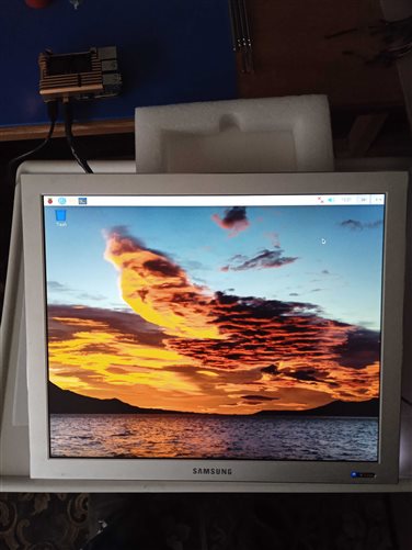
For my project, I decided to use an old 17 inch Samsung Syngmaster 173p monitor as a display. The backlights on this monitor have failed, so I'll have to replace them with LED backlights. To do this, I will use the usual 12v cold glow LED strip with the number of LEDs 120 per meter. I will also have to modify the main monitor board a little, since the monitor and backlights worked from 14v and convert the DVI input to a MicroHDMI plug.

Led backlight
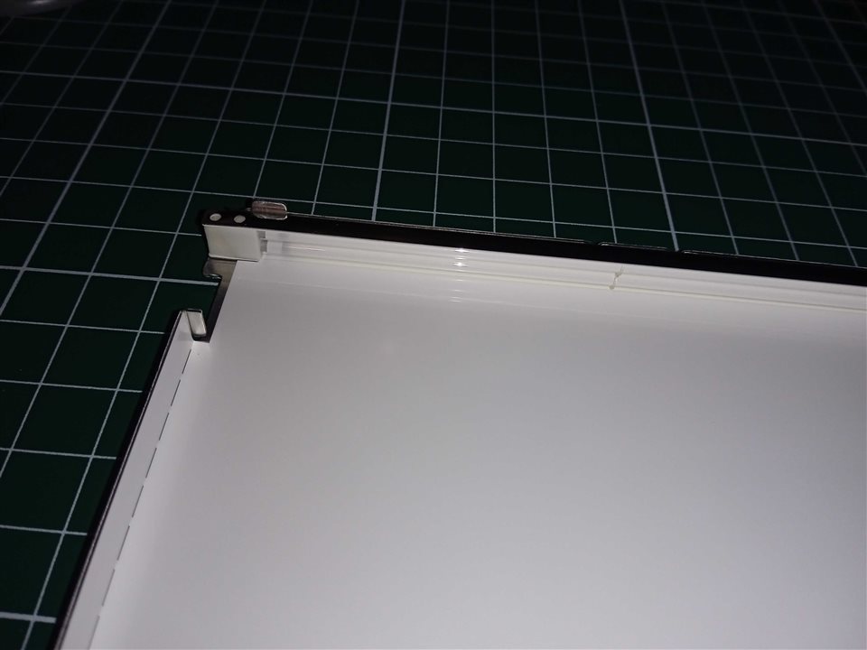
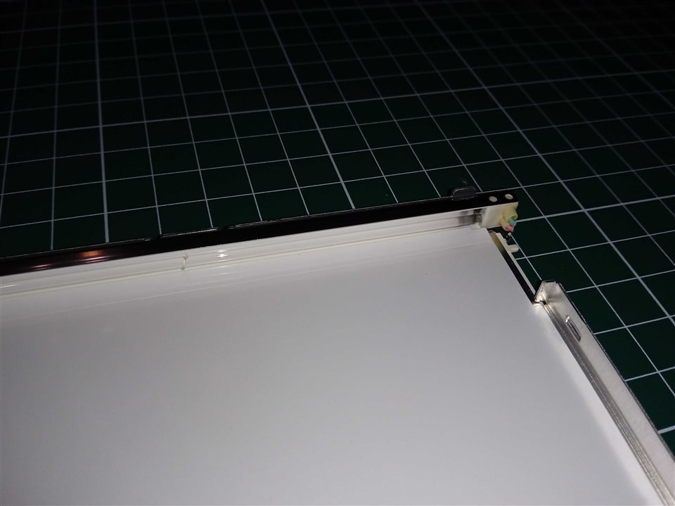
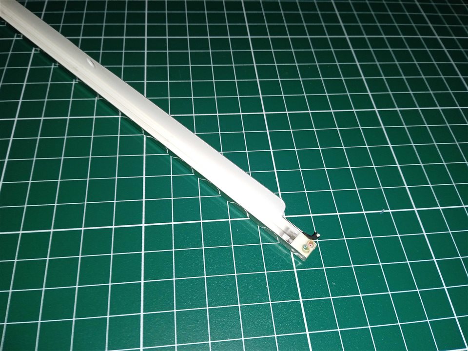
In order to get to the backlights, I disassembled the plastic case, then pulled out and untwisted the metal frame. There is a matrix under the metal frame, I carefully removed it so as not to damage the cables, and under it there are various reflective films, I also carefully took them out in the order in which they lay. Next, there is glass on top and bottom of which there are metal cases in which there are those very burnt lamps that need to be replaced. To do this, I removed them from the cases and installed the LED strip there and put everything back together.

{gallery}Led backlight

image

image

image

image

image

Modification of the monitor board

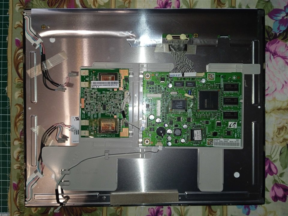
There are two boards installed in the monitor, one main board with a controller and a second inverter board for controlling the backlight lamps. But since I replaced the lamps with a 12v LED strip, the inverter board for controlling the LEDs is not suitable. I found the manual for this monitor and began to figure out how the backlight control works. The inverter board is controlled by only three wires, the first is a 14V power supply for lamps, the second is 5V (BL_EN) turning on the backlight when the monitor is turned on, and the third is a PWM signal (BL_ADJ) to adjust the backlight brightness.

image
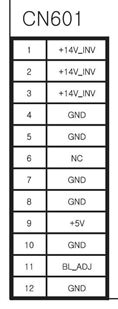
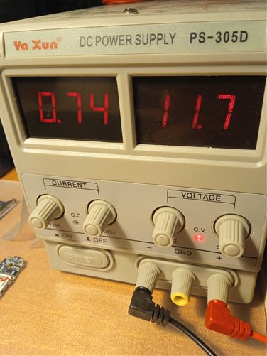
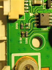
When connecting 12V, the main board works and the monitor turns on, but there is no signal on the 5v(BL_EN), BL_ADJ pins. I began to look at the circuit and saw that the 5v(BL_EN) signal goes through a comparator that compares two 3.3V and 3.7V signals (14v which goes through a voltage divider). But since I connected 12v on the divider, it became 3.2V, so the 5v(BL_EN) signal did not appear. I replaced one of the resistors on the divider so that the voltage became 3.6V and the 5v(BL_EN) signal appeared. Unfortunately, the PWM signal on the BL_ADJ contact did not appear, I do not know what the reason is, who knows, write in the comments. Therefore, you will have to do it without adjusting the backlight (On the other hand, how often do you have to adjust the backlight).

imageimage

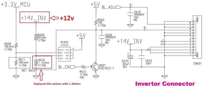
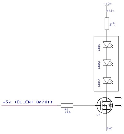
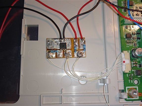
I made the LED backlight switch-on board based on an N-channel field-effect transistor, which I soldered from an old motherboard, with a maximum drain-source voltage of 20 volts, and a current of 10 amps. Each of the tape segments consumes approximately 190 milliamps, so you can use almost any field-effect transistor with a current of at least 0.5 amperes. A signal is sent to the field gate from the +5 V output through a small 100ohm resistor. I decided to supply +12V power to the LED strip through a 10ohm resistor in order to limit the current a little and extend their service life.
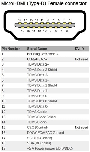
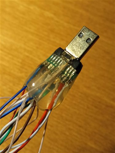
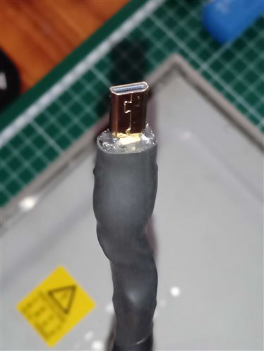
imageimage

DVI to MicroHDMI

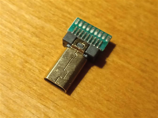
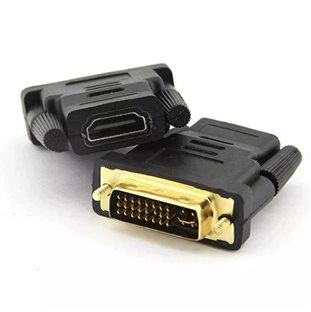
Digital Visual Interface (DVI) is a digital interface that allows you to transfer video images to digital devices, usually a video card monitor. In fact, the difference between HDMI and DVI is a large bandwidth, audio transmission and design differences in the direction of reducing the overall dimensions of the connectors. In the case of the DVI-D modification, only a digital video signal is transmitted, while there is no analog channel. HDMI digital interface, respectively, it will be possible to connect a device to it only with a digital DVI-D connector. If you have a DVI of another modification, then remaking it to HDMI by simply soldering the wires will most likely not work and you will have to make a converter board. I was lucky to use a DVI-D modification in my monitor, so in order not to suffer with adapters, I decided to take the wire that went into the monitor and connected to the main board, cut off the DVI connector and soldered the microHDMI connector according to the pinout.

imageimageimage

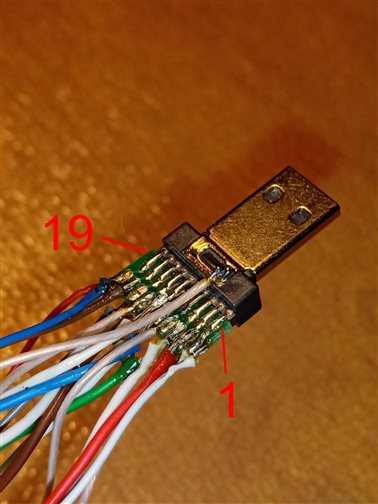
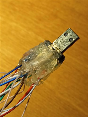
Next, I filled the contacts with PCB varnish and sealed them with a glue gun. Then I heated it with a soldering dryer so that the glue spread well and put on heat shrink.

imageimageimage

image

A small digression. Once upon a time I bought a cheap adapter from DVI to HDMI and wanted to output a picture from a DVI computer to an HDMI TV. But when connected, the picture was with a greenish tinge. I then thought that the adapter was not working properly and did not deal with it for a long time, I threw it into the drawer. After some time, when I began to prepare this project and understand the DVI connector, I remembered about it and decided to check why it was not working properly. When connecting the Raspberry PI through this adapter to the DVI monitor, there was no image at all. I began to ring the contacts and it turned out that this adapter did not have four wires soldered, which are designated as a shield and a common wire to the housing. After I opened it and soldered the necessary wires, the adapter worked. I've seen this problem very often on forums, so keep that in mind.
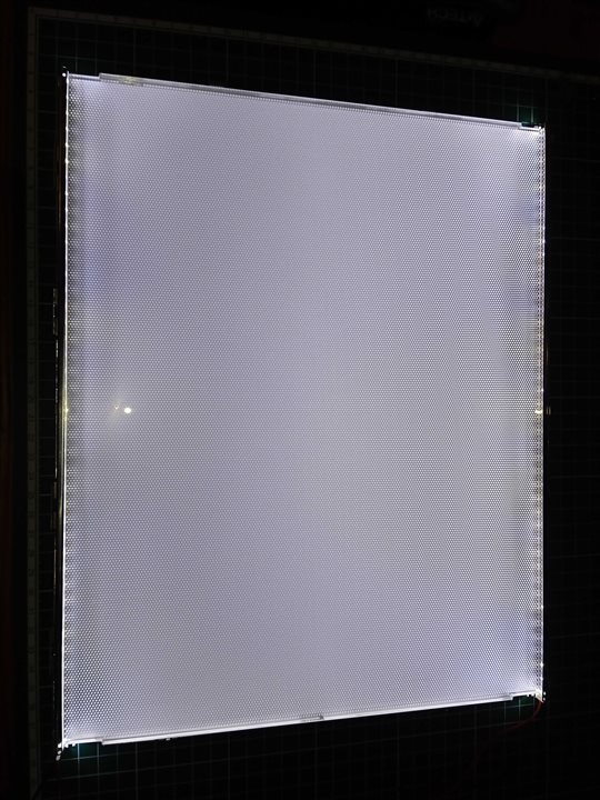
Demonstration

imageimage

  • Sign in to reply
  • soldering.on
    soldering.on over 2 years ago

    Really interesting to see the details of how you repaired and adapted the monitor, I like these old-style aspect ratio screens, I used a similar one with my Pi 3B for a time but using an off the shelf HDMI-VGA adaptor.

    • Cancel
    • Vote Up 0 Vote Down
    • Sign in to reply
    • More
    • Cancel
  • maxpowerr
    maxpowerr over 2 years ago in reply to colporteur

    The adapter that I had was without a 24c164 chip. This adapter was missing connections that I highlighted in red in the diagram (Data_Shield). As I understand it, these connections act as a shield for signal wires from various electrical pickups, that is, metal foil is wound around a pair of Data + and Data- signal wires and the wire is soldered. In the monitor I used for the project, the wire was made exactly like this. When I took the adapter apart, I decided to just solder everything with wires and it all worked.

    imageimage

    • Cancel
    • Vote Up 0 Vote Down
    • Sign in to reply
    • More
    • Cancel
  • colporteur
    colporteur over 2 years ago

    Your Pi video issue using the HDMI to DVI adaptor piqued my interest. I recall having such a problem. I have attached a pic of a DVI connector. Is it possible for you to be more specific on the details you discovered that resolved the issue?

    image

    • Cancel
    • Vote Up 0 Vote Down
    • Sign in to reply
    • More
    • Cancel
element14 Community

element14 is the first online community specifically for engineers. Connect with your peers and get expert answers to your questions.

  • Members
  • Learn
  • Technologies
  • Challenges & Projects
  • Products
  • Store
  • About Us
  • Feedback & Support
  • FAQs
  • Terms of Use
  • Privacy Policy
  • Legal and Copyright Notices
  • Sitemap
  • Cookies

An Avnet Company © 2025 Premier Farnell Limited. All Rights Reserved.

Premier Farnell Ltd, registered in England and Wales (no 00876412), registered office: Farnell House, Forge Lane, Leeds LS12 2NE.

ICP 备案号 10220084.

Follow element14

  • X
  • Facebook
  • linkedin
  • YouTube