

Table of contents

Abstract
We find ourselves juggling multiple tasks be it soldering or managing inventory, having an extra arm would improve efficiency. The Intelligent Extra Arm (IEA) is a novel project that combines hardware, software, and AI to address this problem.
Project
 Intelligent Extra Arm
Introduction
In our daily tasks, we often find ourselves juggling multiple activities simultaneously. Whether it’s soldering electronic components or managing inventory items, having an extra arm would significantly improve efficiency. The challenge lies in creating an intelligent system that seamlessly integrates with our existing workflow. The Intelligent Extra Arm (IEA) is a novel project that combines hardware, software, and AI to address this problem. Let’s break down the key components: We’ll use the Arduino MKR Wifi 1010 as the central controller for the robotic arm. This board provides wireless communication, allowing us to send precise commands to the arm. Our goal is to program the arm to perform tasks such as picking up items from the warehouse or inventory shelves. Alexa integration adds a layer of convenience. Users can issue voice commands to manage the robotic arm. Imagine saying, “Alexa, fetch the soldering wire,” and the arm swings into action. Voice control eliminates the need for physical buttons or switches. The Raspberry Pi serves as the brain of our IEA. Its camera module captures images of items. Leveraging AI algorithms, we’ll identify and classify these items. For example, the system recognizes resistors, capacitors, or other components. TE wire to board connectors and connector housing ensures reliable wiring connections. Push buttons or emergency stop switch allows manual control when needed. The robotic arm’s design should accommodate these components seamlessly.
Workflow Scenario: You’re soldering a circuit board. Suddenly, you need a specific resistor from your inventory. Instead of interrupting your work, you say, “Alexa, fetch the 10kΩ resistor.” The robotic arm locates the resistor, picks it up, and places it within your reach. Meanwhile, the Raspberry Pi identifies the resistor using its camera. Imagine your warehouse shelves. When you need to restock components, Alexa becomes your assistant. “Alexa, check the stock of 1N4148 diodes.” The IEA scans the shelves, updates the inventory database, and alerts you if restocking is necessary.
Below is a pictorial representation of the project.

Object Detection using Edge Impulse
Let's jump right into the project setup. The following forum articles can be referred to for detailed setup instructions - Raspberry Pi Setup - element14 Community and Object Detection using Edge Impulse and Raspberry Pi - element14 Community
First would be setting up the object detection model using Edge Impulse. I had created a new project in this link - https://studio.edgeimpulse.com/studio/profile/projects?autoredirect=1 after logging in or signing up for an Edge Impulse account, by providing project name and selecting project type and setting. After setting up the Raspberry Pi for Edge Impulse, I was able to see the Raspberry Pi device successfully added to my Edge Impulse project. The following are the steps to setup the project,
- Data Acquisition - I was able to successfully test Data Acquisition as well. I have also manually created a bounding box and labelled it as a resistor. Since I'll be using object detection to find items in my inventory. I then sampled a few more pieces of data and made one sample as test data.
- Create Impulse - I then created below Impulse with the following steps - resizing the image to 96x96, an image preprocessing block, then added an object detection learning block, output it automatically selected the name of the items (resistor/ capacitor).
- Image - Then I generated features using the training data set.
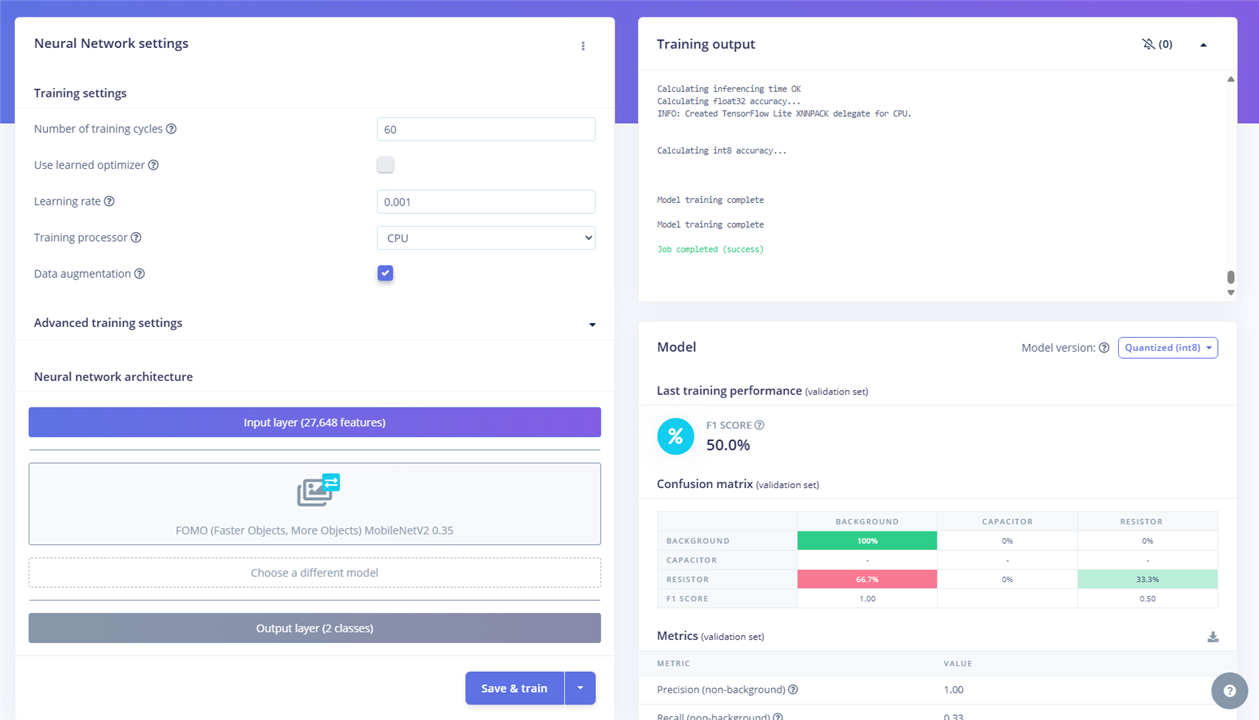
- Object Detection - I then trained the model (FOMO (Faster Objects, More Objects) MobileNetV2 0.35) using the default settings. Refer screenshot in gallery below which shows the training output and model summary.
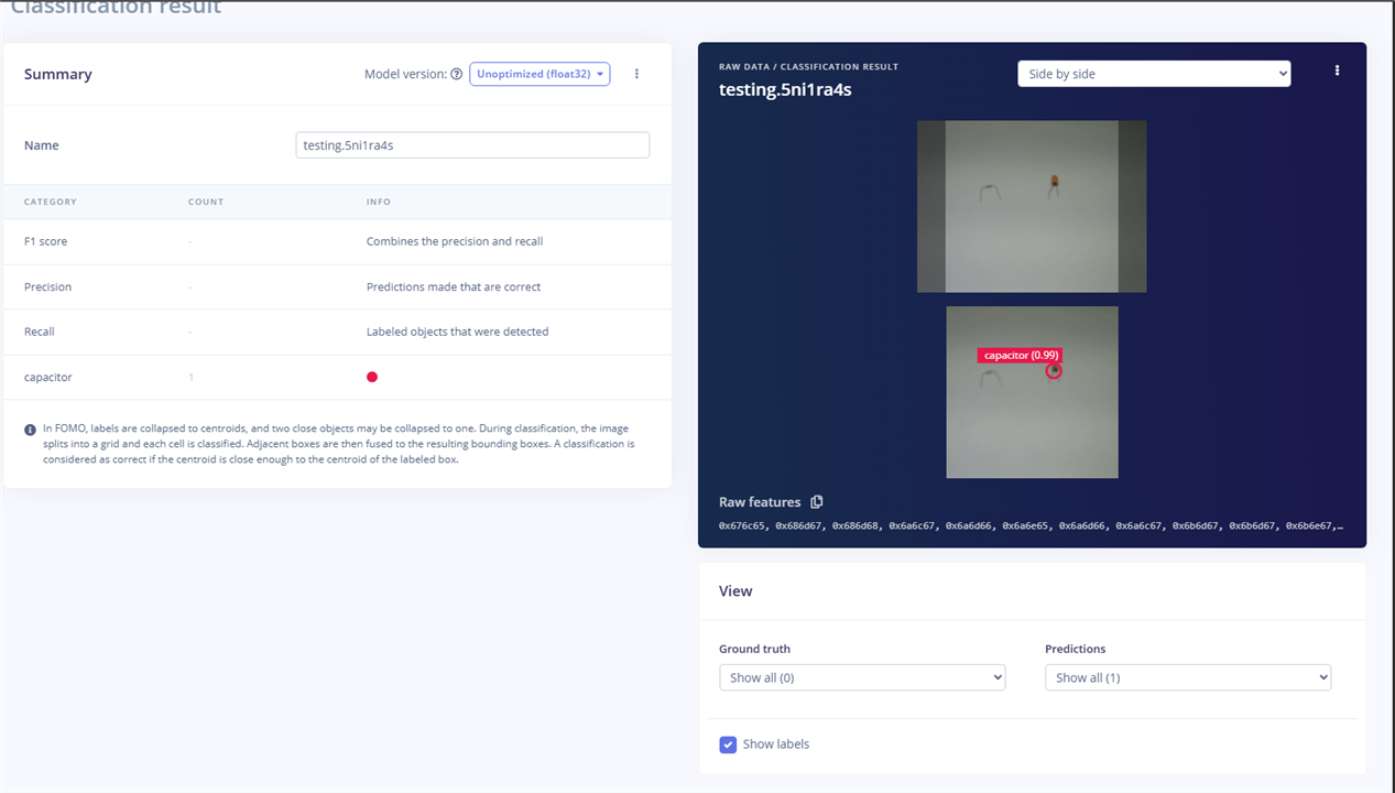
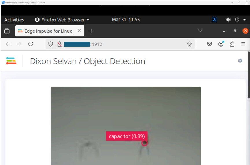
- Live Classification - Then I did a quick live classification and could see the model was able to find the capacitor but not the resistor. Anyways, I'll be loading more dataset and training the model again. For starters, the flow is working as expected. Refer screenshot in gallery below which shows the live classification outcome.
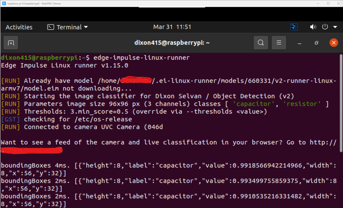
- Execution - Ran the below command in the terminal of Raspberry Pi and refer screenshot in gallery below which shows the outcome of the same.
edge-impulse-linux-runner
| {gallery}Object Detection using Edge Impulse |
|---|
|
Object Detection Model & Training Output |
|
Live Classification |
|
Execution - Raspberry Pi Terminal |
|
Live Classification - Preview |
In case of any challenges, you can refer to this documentation - https://docs.edgeimpulse.com/docs/edge-ai-hardware/cpu/raspberry-pi-4. I have captured retraining information as well in the following forum article - Retraining Object Detection Model - element14 Community
Raspberry Pi Arduino Integration
Now that we have the Edge Impulse - Object Detection model is setup and trained, we need a way to transmit the information to Arduino MKR WiFi 1010 board which will be controlling the robotic arm. For this, I have chosen MQTT and have setup the MQTT server to be running continuously in Raspberry Pi. It will be publishing the classified output - name of the component, confidence of the prediction and location of the bounding boxes which would be the location of the object. Arduino would subscribe to receive this. Below piece of code runs edge-impulse-linux-runner process in the background and the output received from the process can be sent to Arduino.
process = subprocess.Popen(["edge-impulse-linux-runner", "--continuous"], stdout=subprocess.PIPE, stderr=subprocess.PIPE, text=True)
output = process.stdout.readline()
A sample output received from above code is as follows:
boundingBoxes 2ms. [{"height":8,"label":"Capacitor","value":0.9491629004478455,"width":8,"x":8,"y":48},{"height":8,"label":"Resistor","value":0.9932664632797241,"width":8,"x":48,"y":48}]
This is then cleaned/ filtered and the resulting sample information transmitted in the local network is as follows:
{"label": "Resistor", "confidence": 0.9869165420532227, "position": {"x": 16, "y": 8}}
{"label": "Diode", "confidence": 0.9637554883956909, "position": {"x": 8, "y": 24}}
{"label": "Capacitor", "confidence": 0.9629590511322021, "position": {"x": 40, "y": 40}}
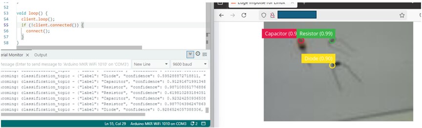
Below image shows on the right Raspberry Pi showing preview of live classification and to the left is Arduino IDE Serial monitor showing the classified output received at Arduino's end.
I had also setup Node-RED in Raspberry pi and allowed it to run continuously as a background service. This is to test the MQTT publish/ subscribe setup.As you can see in the below screenshot, I have setup two publish nodes. Classification_topic: this is to share the classified output to Arduino and alexa_topic: this is to share what component was asked to be picked up. The alexa_topic will be discussed further in the next section. I have connected this to debug node for printing out the message or payload received. The other nodes are there for test purposes to check the MQTT publish/ subscribe initially.

Refer this documentation for further information required on MQTT and Node-Red setup for IOT devices - https://docs.arduino.cc/tutorials/projects/control-your-iot-cloud-kit-via-mqtt-and-node-red/ and https://nodered.org/docs/getting-started/raspberrypi
Arduino Alexa Integration
Moving on to the next step. For communicating between Alexa and Arduino I had to take a long route because of some challenges and time constraint I had. Initially as I had mentioned in this forum article - Arduino MKR WiFi 1010 and Alexa Integration - element14 Community, I had setup integration between Arduino and Alexa through Arduino IOT Cloud and Alexa mobile app. But this is restricted to inputs like true/ false and ON/ OFF mostly to control smart home devices.
The voice command received at Alexa triggers IFTTT webhook which then saves the information in a Google Sheet. This is read at an interval of 1 second by Raspberry Pi and publishes the component which has to be picked up in an MQTT topic. Arduino which has subscribed to this topic receives this information and takes action accordingly. This is in short, let's now see it in detail.
Alexa Developer Console
First, let's create a custom Alexa skill in Alexa Developer Console - https://developer.amazon.com/alexa/console/ask. I have created it as a custom skill instead of going with the pre-defined templates is that I need to modify according to my requirement. After naming, selecting the hosting etc, once the skill creation is completed, I went to configure the Intents first. I have added the following intent - pick {component} where component can be replaced with any text, let's say pick resistor, pick capacitor like that.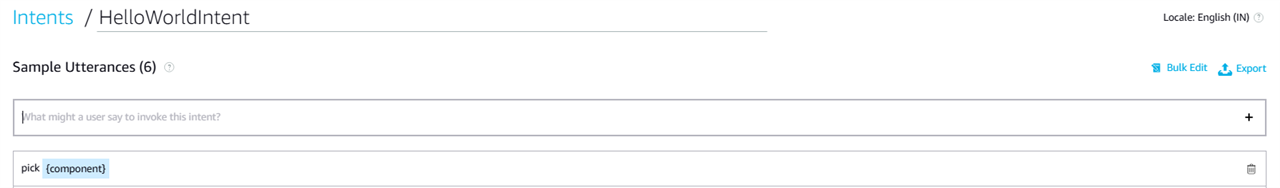
After this, in the code section, I have added below code to call the IFTTT webhook.
const https = require('https');

const API_URL = "https://maker.ifttt.com/trigger/<<YOUREVENT>>/json/with/key/<<YOURKEY>>";

const HelloWorldIntentHandler = {
    canHandle(handlerInput) {
        return Alexa.getRequestType(handlerInput.requestEnvelope) === 'IntentRequest'
            && Alexa.getIntentName(handlerInput.requestEnvelope) === 'HelloWorldIntent';
    },
    async handle(handlerInput) {
        const component = handlerInput.requestEnvelope.request.intent.slots.component.value;
        await sendToArduino(component);
        const speechText = `Picking ${component}!`;
        return handlerInput.responseBuilder
            .speak(speechText)
            .getResponse();
    }
};
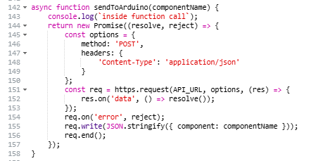
Strangely, I was not able to add the code of sendToArduino function or attach a .js file. So, I have added it as a screenshot below.
After this, I had deployed and tested it in the simulation tool available. Below screenshot shows the dialog flow.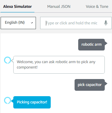
IFTTT and Google Sheets
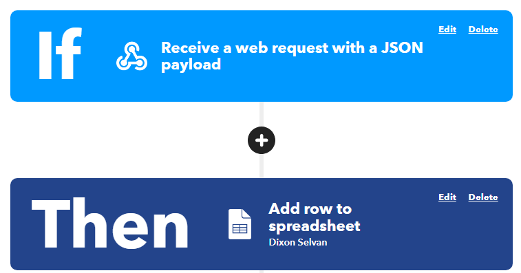
Now, let's move on to see the setup of IFTTT and Google Sheets. In IFTTT, I created a new applet with the setting shown below. Alexa will trigger a POST request to the IFTTT Webhook with JSON payload having the component name. This will be then added as a new row in the Google Sheets with some additional information like date created.
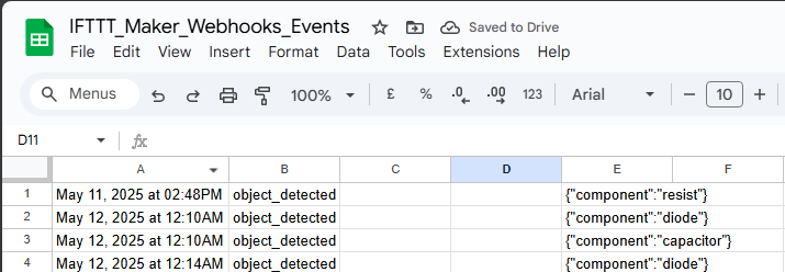
Below screenshot shows the information captured finally in the Google Sheet. Column A - date created, Column B - event name, Column C - JSON payload.
I had to create below script for exposing this information in a GET request in Google Sheets - App Script. This will be called by Raspberry Pi and the information received in response will be sent further to Arduino as explained in the previous section end (refer related to alexa_topic).
function doGet(e) {
  var sheet = SpreadsheetApp.getActiveSpreadsheet().getActiveSheet();
  var lastRow = sheet.getLastRow(); // Get last row with data
  var columnNumber = 5; // Change this to your desired column index
  var modifiedColumnNumber = 1;

  var lastColumnValue = sheet.getRange(lastRow, columnNumber).getValue();
  Logger.log("Last Row Value in Column " + columnNumber + ": " + lastColumnValue);

  var lastModifiedValue = sheet.getRange(lastRow, modifiedColumnNumber).getValue();
  Logger.log("Last Row Value in Column " + modifiedColumnNumber + ": " + lastModifiedValue);

  var output = { lastColumnValue, lastModifiedValue };
  return ContentService.createTextOutput(JSON.stringify(output))
                         .setMimeType(ContentService.MimeType.JSON);
}
# Python Code for GET request
response = requests.request("GET", url, headers=headers, data=payload)
Robotic Arm Setup
Forum Article for Reference - Robotic Arm - Assembly, Wiring and Programming - element14 Community
With model and integrations completed, let's now jump into the hardware section and for starter let's assemble the 3D printed parts of the robotic arm. I hadn't used the 3D printer I had for many months. After that, it was functional for a while until I used it one day and it stopped turning ON. So, I couldn't 3D print the robotic arm myself. I purchased the 3D printed parts of the robotic arm gripper in Amazon and it turned out to be much better than I expected at a reasonable price. Below is a stop motion video showing the assembly of the robotic arm.
Now that I have the skeleton or the structure of the robotic arm, let's give it some life! I meant the functioning parts - Servo motors, wires to connect and Arduino MKR WiFi 1010 to control. I have used four SG-90 servo motors to move the robotic arm parts, and it seems to work without any hassle. One servo motor rotates the robotic arm, another controls the gripper and two for up and down movement with some stretches front and back. This way I could use this robotic arm to grasp the object I would need.
For connecting the wires, I have utilized the TE Connectivity crimp terminal and connector housing (male and female) provided as part of the kit. Only one TE Connectivity female crimp terminal was provided to me in the kit. So, I had purchased few male and female crimp terminals, crimping tool in Amazon along with some Berg connector housing. Also, another reason for choosing this way of connecting wires was because I had kept jumper wires in a 3D printed (PLA) organizer inside a plastic container and haven't opened it or used it for quite a long time. The result of which I could see some plastic decomposition/ some residue settling down on the jumper ends leading to connectivity issues. I even tried showing the ends to the flame in an attempt to melt or burn them away. But still the connectivity was not as expected and there were frequent disconnections.
Below are some pictures to show the side effects of leaving the 3D printed organizer to decompose and cause some residue in the jumper ends.

Below is the circuit diagram/ representation of the Robotic Arm (some might not be actual representations of the parts used and are a close match). I had initially used single core wires throughout the circuit, but it seems to disconnect very often making the responses of the robotic Arm unstable to the input provided. As a result, I have done the wiring again with multicore wires. Now, the robotic arm is stable and works as expected.
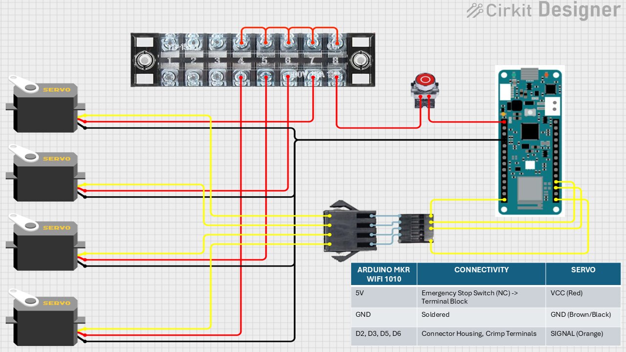
I have used the TE Connectivity terminal block and Emergency stop switch in the 5V connection to the Servo from Arduino. All the red/ VCC wires from the servo motors are connected to the terminal blcok and one wire is connected to 5V of Arduino through the Emergency stop switch (NC). When I connect or plug in the Arduino, there are some signals passed to the robotic arm causing it to stumble at times. So, I have connected an emergency stop switch to stop this while turning it ON or powering up and later allow the circuit to behave as expected. Also, it can be used in case of emergency situations which gets out of hand.
All the ground wires are soldered together.
All the signal wires are connected to D2, D3, D5 and D6 pins of the Arduino through TE Connectivity crimp terminal (other brand also) inside TE Connectivity connector housing (male and female). This way we can easily connect and disconnect when required.
Below video shows the entire wiring process along with the challenges faced. I have built a case to hold the robotic arm's control unit - Arduino MKR WiFi 1010, terminal block and emergency stop switch including the wiring. The second video below is a quick video showing the case.
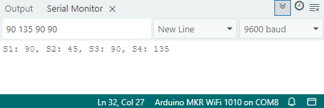
For quick testing purpose, I've written below code which uses serial connection to send the angles which I want each of the servos to rotate to. We can use it to test the servos individually as well by providing the last angle which was provided to the other servos. Be careful while giving the angles which might be obstructed by another servo as in the case of the two servos controlling the up, down, front, and back motion.
The input and output example can be seen below. I have used the Arduino IDE installed in my laptop and opened the serial monitor section for this.
#include <Servo.h>

Servo s1, s2, s3, s4;

void setup() {
  Serial.begin(9600);
  s1.attach(2);
  s2.attach(3);
  s3.attach(5);
  s4.attach(6);
}

void loop() {
  if (Serial.available() > 0) {
    String input = Serial.readStringUntil('\n');
    input.trim();
    int angles[4];

    int index = 0;
    char* token = strtok((char*)input.c_str(), " ");

    while (token != NULL && index < 4) {
      angles[index++] = atoi(token);
      token = strtok(NULL, " ");
    }

    if (index == 4) {
      char buffer[50];
      s1.write(angles[0]);
      s2.write(angles[1]);
      s3.write(angles[2]);
      s4.write(angles[3]);
      sprintf(buffer, "S1: %d, S2: %d, S3: %d, S4: %d", angles[0], angles[1], angles[2], angles[3]);
      Serial.println(buffer);
    } else {
      Serial.println("Invalid input!");
    }
  }
}
Intelligent Extra Arm - In Action!
It's show time, let's see in below video Intelligent Extra Arm in action.
Code
I have provided below the complete Arduino and Raspberry Pi codes used for this project. Other code which was used as part of the project has been shared above in respective sections where it was used.
Arduino Code
#define BROKER_IP    "x.x.x.x"
#define DEV_NAME     "client-name"
#define MQTT_USER    "user-name"
#define MQTT_PW      "user-password"
#define MQTT_MAX_PACKET_SIZE 1024

const char ssid[] = "your-ssid";
const char pass[] = "your-password";

#include <ArduinoJson.h>
#include <MQTT.h>
#include <WiFiNINA.h>
#include <map>
#include <string>
#include <algorithm>
#include <Servo.h>

WiFiClient net;
MQTTClient client;

struct Component {
    std::string label;
    float confidence;
    int posX;
    int posY;
};
std::map<std::string, Component> componentMap;

Servo gripperServo;  // Servo 1 (Gripper)
Servo armServo1;     // Servo 2 (Up/Down)
Servo armServo2;     // Servo 3 (Up/Down)
Servo baseServo;     // Servo 4 (Rotation)

const int gripperPin = 2;
const int arm1Pin = 3;
const int arm2Pin = 5;
const int basePin = 6;

const int basePositionA = 90;  // Rotation at Location A
int basePositionB = 0; // Rotation at Location B

const int arm1UpPosition = 130;   // Arm lifted
const int arm2UpPosition = 90;   // Arm lifted
const int arm1DownPosition = 90; // Arm lowered
const int arm2DownPosition = 130; // Arm lowered

const int gripperOpen = 135;  // Open gripper
const int gripperClosed = 90; // Close gripper

const int stepDelay = 10; // Delay between steps

void storeData(const char* topic, const char* jsonPayload) {
    StaticJsonDocument<200> doc;
    deserializeJson(doc, jsonPayload);

    Component comp;
    comp.label = doc["label"].as<std::string>();
    comp.confidence = doc["confidence"].as<float>();
    comp.posX = doc["position"]["x"].as<int>();
    comp.posY = doc["position"]["y"].as<int>();

    componentMap[comp.label] = comp;
}

Component getComponentData(const std::string& label) {
    if (componentMap.find(label) != componentMap.end()) {
        return componentMap[label];
    } else {
        return {"", 0.0, 0, 0};  // Return an empty component if not found
    }
}

void printComponentMap() {
    Serial.println("Stored components:");

    for (const auto& pair : componentMap) {
        Serial.print("Label: ");
        Serial.println(pair.second.label.c_str());

        Serial.print("Confidence: ");
        Serial.println(pair.second.confidence);

        Serial.print("Position: (");
        Serial.print(pair.second.posX);
        Serial.print(", ");
        Serial.print(pair.second.posY);
        Serial.println(")");

        Serial.println("---------------------");
    }
}

void connect() {
  Serial.print("checking wifi...");
  while (WiFi.status() != WL_CONNECTED) {
    Serial.print(".");
    delay(1000);
  }
  Serial.print("\nconnecting...");
  while (!client.connect(DEV_NAME, MQTT_USER, MQTT_PW)) {
    Serial.print(".");
    delay(1000);
  }
  Serial.println("\nconnected!");
  client.subscribe("classification_topic");
  client.subscribe("alexa_topic");
}

void messageReceived(String &topic, String &payload) {
  //Serial.println("incoming: " + topic + " - " + payload);
  if (topic == "alexa_topic") {
    Serial.println("incoming: " + topic + " - " + payload);
    //printComponentMap();
    std::string cppString = payload.c_str();
    std::transform(cppString.begin(), cppString.end(), cppString.begin(), ::tolower);
    // Capitalize the first letter
    if (!cppString.empty()) {
        cppString[0] = toupper(cppString[0]);
    }
    Component retrieved = getComponentData(cppString);
    Serial.print("Label: ");
    Serial.println(retrieved.label.c_str());
    Serial.print("Confidence: ");
    Serial.println(retrieved.confidence);
    Serial.print("Position: (");
    Serial.print(retrieved.posX);
    Serial.print(", ");
    Serial.print(retrieved.posY);
    Serial.println(")");
    pickComponent(retrieved.posY);
  } else if (topic == "classification_topic") {
    storeData(topic.c_str(), payload.c_str());
  }
}

void gradualMove(Servo &servo, int startPos, int endPos) {
  int step = (startPos < endPos) ? 1 : -1;  // Determine direction
  for (int pos = startPos; pos != endPos; pos += step) {
      servo.write(pos);
      delay(stepDelay);
  }
  servo.write(endPos);  // Ensure final position is reached
}

int getBasePosition(int y) {
  //This is not a hardcoded location of the components, just returning three possible base locations to pick from
  if (y >= 0 && y <= 20) return 0;
  else if (y > 20 && y <= 40) return 10;
  else if (y > 40 && y <= 60) return 20;
  return 0;
}

void pickComponent(int y) {
  basePositionB = getBasePosition(y);
  // Move to Location B
  Serial.println("Moving to Location B...");
  baseServo.write(basePositionB);
  //gradualMove(baseServo, basePositionA, basePositionB);
  delay(1000);

  // Lower arm
  Serial.println("Lowering arm...");
  gradualMove(armServo1, arm1UpPosition, arm1DownPosition);
  gradualMove(armServo2, arm2UpPosition, arm2DownPosition);
  delay(1000);

  // Close gripper (pick item)
  Serial.println("Picking up item...");
  gradualMove(gripperServo, gripperOpen, gripperClosed);
  delay(1000);

  // Lift arm
  Serial.println("Lifting item...");
  armServo1.write(arm1UpPosition);
  armServo2.write(arm2UpPosition);
  //gradualMove(armServo1, arm1DownPosition, arm1UpPosition);
  //gradualMove(armServo2, arm2DownPosition, arm2UpPosition);
  delay(1000);

  // Move back to Location A
  Serial.println("Returning to Location A...");
  baseServo.write(basePositionA);
  //gradualMove(baseServo, basePositionB, basePositionA);
  delay(1000);

  // Lower arm
  Serial.println("Lowering arm...");
  gradualMove(armServo1, arm1UpPosition, arm1DownPosition);
  gradualMove(armServo2, arm2UpPosition, arm2DownPosition);
  delay(1000);

  // Open gripper (drop item)
  Serial.println("Dropping item...");
  gradualMove(gripperServo, gripperClosed, gripperOpen);
  delay(1000);

  // Lift arm back up
  Serial.println("Resetting arm...");
  armServo1.write(arm1UpPosition);
  armServo2.write(arm2UpPosition);
  //gradualMove(armServo1, arm1DownPosition, arm1UpPosition);
  //gradualMove(armServo2, arm2DownPosition, arm2UpPosition);
  delay(2000);
}

void setup() {
  Serial.begin(9600);
  WiFi.begin(ssid, pass);
  client.begin(BROKER_IP, 1883, net);
  client.onMessage(messageReceived);
  connect();

  gripperServo.attach(gripperPin);
  armServo1.attach(arm1Pin);
  armServo2.attach(arm2Pin);
  baseServo.attach(basePin);

  baseServo.write(basePositionA);
  armServo1.write(arm1UpPosition);
  armServo2.write(arm2UpPosition);
  gripperServo.write(gripperOpen);

  delay(2000);
}

void loop() {
  client.loop();
  if (!client.connected()) {
    connect();
  }
}
Raspberry Pi Code
import paho.mqtt.client as mqtt
import subprocess
import time
import json
import re
import requests
import threading

mqtt_broker = "x.x.x.x"
mqtt_port = 1883
mqtt_topic = "classification_topic"
mqtt_alexa_topic = "alexa_topic"
url = "https://script.google.com/macros/s/YOURKEY/exec"

client = mqtt.Client()
client.connect(mqtt_broker, mqtt_port, 60)
payload = {}
headers = {}
last_seen_objects = {}
previous_modified_value = None
process = subprocess.Popen(["edge-impulse-linux-runner", "--continuous"], stdout=subprocess.PIPE, stderr=subprocess.PIPE, text=True)

def process_payload(payload):
    json_start = payload.find("[")
    if json_start == -1:
        print("Invalid JSON format!")
        return
    json_payload = payload[json_start:]
    try:
        bounding_boxes = json.loads(json_payload)
    except json.JSONDecodeError:
        print("Failed to parse JSON!")
        return ""
    data_to_publish = {"detected_objects": []}
    for box in bounding_boxes:
        data_to_publish["detected_objects"].append({
            "label": box.get("label", "Unknown"),
            "confidence": box.get("value", 0.0),
            "position": {"x": box.get("x", 0), "y": box.get("y", 0)}
        })
    json_output = json.dumps(data_to_publish)
    return json_output

def process_stream_data(json_string):
    global last_seen_objects
    data = json.loads(json_string)
    filtered_objects = {(obj["label"], obj["position"]["x"], obj["position"]["y"]) for obj in data["detected_objects"]}
    if filtered_objects != last_seen_objects:
        last_seen_objects = filtered_objects
        return(json.dumps(data))

def publishClassificationOutput():
	output = process.stdout.readline()
	#print(output)
	if "boundingBoxes" in output:
		cleaned_output = re.split(r"boundingBoxes \d+ms\. ", output)[-1]
		bounding_boxes = process_payload(cleaned_output)
		filtered_bounding_boxes = process_stream_data(bounding_boxes)
		if filtered_bounding_boxes:
			data = json.loads(filtered_bounding_boxes)
			if data:
				for obj in data.get("detected_objects"):
					json_payload = json.dumps(obj)
					client.publish(mqtt_topic, json_payload)
					print(f"Published: {json_payload}")

def publishAlexaRequestData():
	global previous_modified_value
	response = requests.request("GET", url, headers=headers, data=payload)
	if response:
		data = json.loads(response.text)
		if data:
			current_modified_value = data["lastModifiedValue"]
			# Check if lastModifiedValue has changed
			if current_modified_value != previous_modified_value:
				inner_dict = json.loads(data["lastColumnValue"])
				component_name = inner_dict["component"]
				# Update previous_modified_value for future comparisons
				previous_modified_value = current_modified_value
				client.publish(mqtt_alexa_topic, component_name)
				return component_name
			else:
				return ""
		else:
			return ""
	else:
		return ""


def classification_loop():
	while True:
		publishClassificationOutput()

def alexa_loop():
	while True:
		output = publishAlexaRequestData()
		if output:
			print(output)
		time.sleep(1)

# Run the fetch_data function in a separate thread
classification_thread = threading.Thread(target=classification_loop, daemon=True)
alexa_thread = threading.Thread(target=alexa_loop, daemon=True)
classification_thread.start()
alexa_thread.start()

# Keeping the main thread alive
while True:
    time.sleep(10)
Do let me know your valuable comments and feedback of this project in the comments section. Thanks for reading this far!
References
Forum Articles
Intelligent Extra Arm (IEA) - Project Introduction
Arduino MKR WiFi 1010 and Alexa Integration
Object Detection using Edge Impulse and Raspberry Pi
Retraining Object Detection Model
Robotic Arm - Assembly, Wiring and Programming
References (Images)
- Arduino MKR 1010 - docs.arduino.cc/hardware/mkr-wifi-1010/
- ALCOSWITCH - TE CONNECTIVITY PBES16L1BR - https://in.element14.com/te-connectivity/pbes16l1br/e-stop-switch-spst-nc-3a-125vac/dp/3773365
- TE CONNECTIVITY 1-2366515-8 - https://in.element14.com/te-connectivity/1-2366515-8/connector-housing-rcpt-8pos-2mm/dp/3787088
- TE CONNECTIVITY 2367818-2 - https://in.element14.com/te-connectivity/2367818-2/contact-socket-22-28awg-crimp/dp/3787098
- TE CONNECTIVITY 1-2366600-8 - https://in.element14.com/te-connectivity/1-2366600-8/connector-housing-rcpt-8pos-2mm/dp/3787090
- TE CONNECTIVITY 1473562-8 - https://in.element14.com/te-connectivity/1473562-8/plug-yellow-8pole/dp/1077398
- ALCOSWITCH - TE CONNECTIVITY TPA11CGRA004 - https://in.element14.com/alcoswitch-te-connectivity/tpa11cgra004/switch-spst-mom/dp/1123975
- Robotic arm - https://pixabay.com/illustrations/robot-machine-robotics-technology-7925618/
- Amazon Alexa Echo Dot - https://unsplash.com/photos/2nd-gen-black-and-purple-amazon-echo-dot-on-white-surface-bifCXiN5rdY
- Raspberry Pi - https://pixabay.com/photos/raspberry-pi-computer-electronics-572481/
- Raspberry Pi Camera - https://www.raspberrypi.com/documentation/accessories/camera.html