


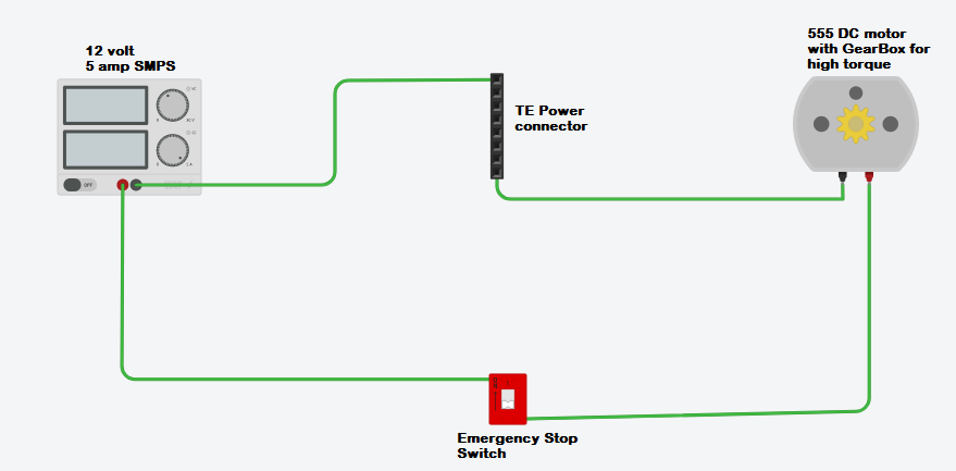
This heavy duty PCB cutter requires 12 volt supply and around 5 amp for it's DC motor to work. The DC motor has gearbox to increase it's torque. The DC motor is a 555 DC motor. Bellow is the schematic diagram for the electrical circuit with an emergency stop switch.
Schematic
Steps for assembling the electrical system
Step 1:-
Building Aluminum Faceplate for Stop Switch. For building Aluminum faceplate for attaching stop switch in it. We first drill holes in each corner for screwing four screw through that hole on the wooden plank on the PCB cutter. After that we make a large hole at the center which allows the stop switch to be attached. As shown in Video bellow.
Know we check weather the stop switch can pass through hole or not. Which is shown in the video bellow.
Step 2:-
In this step, we are going to Drill a hole on the wooden plank of the PCB cutter. So that the bottom part of the Stop Switch can pass through it. Video bellow shows, how we have drilled holes on the plank.
Step 3:-
In this step, we will attach stop switch to the wooden Plank of the PCB cutter. Shown in video bellow
Step 4:-
In this step we connect the line connector provided by TE on the PCB cutter as shown in video bellow.
Step 5:-
In this step we do the wiring as provided in the Schematic diagram above.