I have updated the buzzer to a larger buzzer with louder sound and it is an active buzzer. bellow is the video of the buzzer and sound of it.
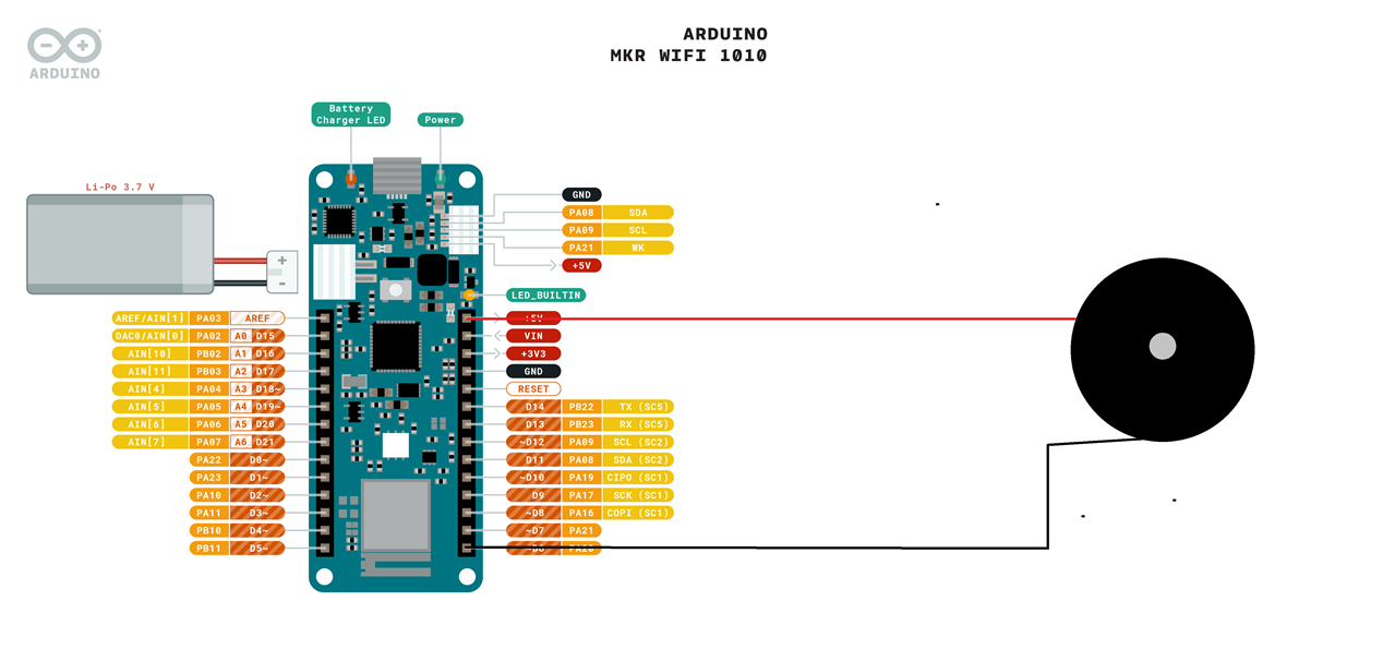
For buzzer to work, we have connected the -ve terminal of the buzzer to IO PIN 6 and positive terminal of it to 5 volt of mkr wifi 1010 board. Bellow is the connection image of it.
Arduino code for testing the buzzer
// the setup function runs once when you press reset or power the board
void setup() {
  // initialize digital pin LED_BUILTIN as an output.
  pinMode(LED_BUILTIN, OUTPUT);
}

// the loop function runs over and over again forever
void loop() {
  digitalWrite(LED_BUILTIN, HIGH);   // turn the LED on (HIGH is the voltage level)
  delay(1000);                       // wait for a second
  for(int a = 0; a<5; a++){
                            digitalWrite(LED_BUILTIN, LOW);    // turn the LED off by making the voltage LOW
                            delay(100);
                            digitalWrite(LED_BUILTIN, HIGH);   // turn the LED on (HIGH is the voltage level)
                            delay(100);
                            }
}
Setting up and testing RTD temperature sensor.
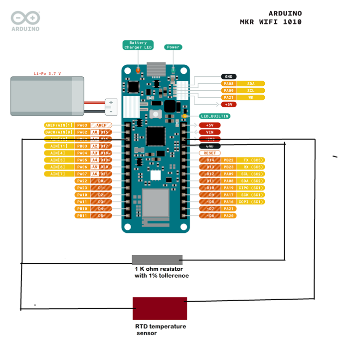
For setting up RTD we have build a voltage divider with RTD using 1% tolerance resistor of 1 K ohm. Bellow is the circuit diagram of connecting the RTD.
Bellow is the code for testing the temperature sensor.
// the setup function runs once when you press reset or power the board
void setup() {
    //Serial Setup
  Serial.begin(9600);
  while (!Serial);  // Wait for Serial monitor to open

}

// the loop function runs over and over again forever
void loop() {

       //Serial Read Write
       int rawValue = analogRead(A1);
  float voltage = rawValue * (3.3 / 1023.0);  // Convert to voltage

  Serial.print("Raw ADC Value: ");
  Serial.print(rawValue);
  Serial.print(" => Voltage: ");
  Serial.print(voltage, 3);  // 3 decimal places
  Serial.println(" V");
}
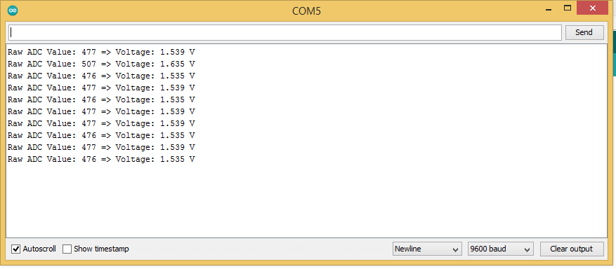
Output of the temperature sensor in serial monitor of arduino.
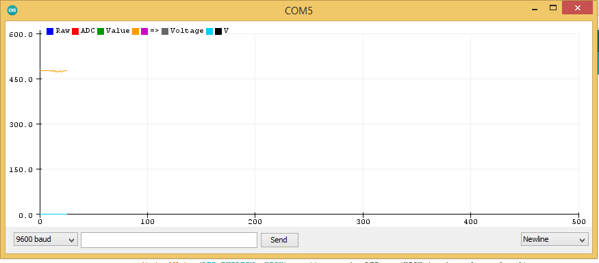
Output of RTD sensor in Serial plotter.