


 Intelligent Extra Arm
Robotic Arm
In the last two forum discussions, I completed the Object Detection model setup, training and re-training using Edge Impulse and Raspberry Pi connected to a USB Webcam. In this forum discussion, I'll proceed with the robotic arm assembly, wiring and programming. This will help constitute the main arm part of the Intelligent Extra Arm which will pick up the objects identified from its location and hand it over to me in a different location where I'll be busy working let's say soldering.
Assembly
In this section, let's assemble the 3D printed parts of the robotic arm. I hadn't used the 3D printer I had for many months. After that, it was functional for a while until I used it one day and it stopped turning ON. So, I couldn't 3D print the robotic arm myself. I purchased the 3D printed parts of the robotic arm gripper in Amazon and it turned out to be much better than I expected at a reasonable price. Below is a stop motion video showing the assembly of the robotic arm.
Wiring
Now that I have the skeleton or the structure of the robotic arm, let's give it some life! I meant the functioning parts - Servo motors, wires to connect and Arduino MKR WiFi 1010 to control. I have used four SG-90 servo motors to move the robotic arm parts, and it seems to work without any hassle. One servo motor rotates the robotic arm, another controls the gripper and two for up and down movement with some stretches front and back. This way I could use this robotic arm to grasp the object I would need.
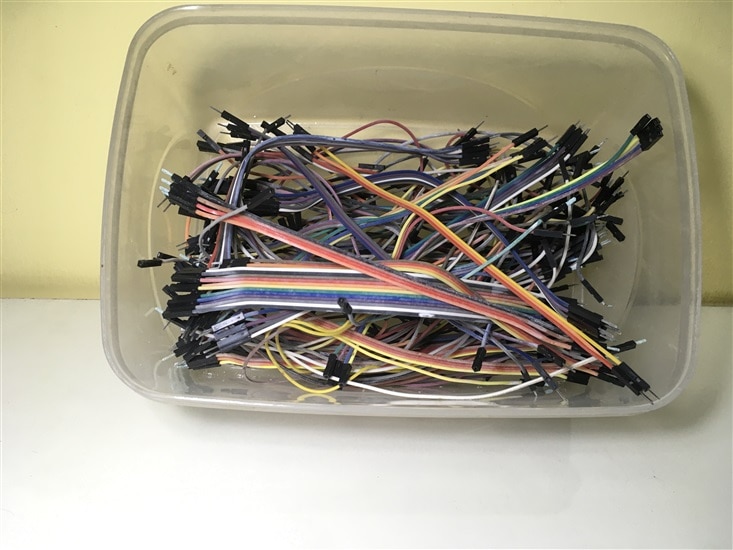
For connecting the wires, I have utilized the TE Connectivity crimp terminal and connector housing (male and female) provided as part of the kit. Only one TE Connectivity female crimp terminal was provided to me in the kit. So, I had purchased few male and female crimp terminals, crimping tool in Amazon along with some Berg connector housing. Also, another reason for choosing this way of connecting wires was because I had kept jumper wires in a 3D printed (PLA) organizer inside a plastic container and haven't opened it or used it for quite a long time. The result of which I could see some plastic decomposition/ some residue settling down on the jumper ends leading to connectivity issues. I even tried showing the ends to the flame in an attempt to melt or burn them away. But still the connectivity was not as expected and there were frequent disconnections.
Below are some pictures to show the side effects of leaving the 3D printed organizer to decompose and cause some residue in the jumper ends.

Below is the circuit diagram/ representation of the Robotic Arm (some might not be actual representations of the parts used and are a close match). I had initially used single core wires throughout the circuit, but it seems to disconnect very often making the responses of the robotic Arm unstable to the input provided. As a result, I have done the wiring again with multicore wires. Now, the robotic arm is stable and works as expected.
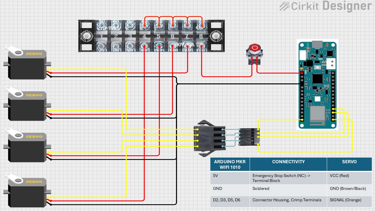
I have used the TE Connectivity terminal block and Emergency stop switch in the 5V connection to the Servo from Arduino. All the red/ VCC wires from the servo motors are connected to the terminal blcok and one wire is connected to 5V of Arduino through the Emergency stop switch (NC). When I connect or plug in the Arduino, there are some signals passed to the robotic arm causing it to stumble at times. So, I have connected an emergency stop switch to stop this while turning it ON or powering up and later allow the circuit to behave as expected. Also, it can be used in case of emergency situations which gets out of hand.
All the ground wires are soldered together.
All the signal wires are connected to D2, D3, D5 and D6 pins of the Arduino through TE Connectivity crimp terminal (other brand also) inside TE Connectivity connector housing (male and female). This way we can easily connect and disconnect when required.
Below video shows the entire wiring process along with the challenges faced.
Programming
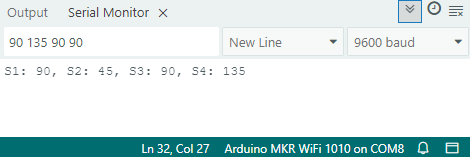
For quick testing purpose, I've written below code which uses serial connection to send the angles which I want each of the servos to rotate to. We can use it to test the servos individually as well by providing the last angle which was provided to the other servos. Be careful while giving the angles which might be obstructed by another servo as in the case of the two servos controlling the up, down, front, and back motion.
#include <Servo.h>

Servo s1, s2, s3, s4;

void setup() {
  Serial.begin(9600);
  s1.attach(2);
  s2.attach(3);
  s3.attach(5);
  s4.attach(6);
}

void loop() {
  if (Serial.available() > 0) {
    String input = Serial.readStringUntil('\n');
    input.trim();
    int angles[4];

    int index = 0;
    char* token = strtok((char*)input.c_str(), " ");

    while (token != NULL && index < 4) {
      angles[index++] = atoi(token);
      token = strtok(NULL, " ");
    }

    if (index == 4) {
      char buffer[50];
      s1.write(angles[0]);
      s2.write(angles[1]);
      s3.write(angles[2]);
      s4.write(angles[3]);
      sprintf(buffer, "S1: %d, S2: %d, S3: %d, S4: %d", angles[0], angles[1], angles[2], angles[3]);
      Serial.println(buffer);
    } else {
      Serial.println("Invalid input!");
    }
  }
}
The input and output example can be seen below. I have used the Arduino IDE installed in my laptop and opened the serial monitor section for this.
Case
I have built a case to hold the robotic arm's control unit - Arduino MKR WiFi 1010, terminal block and emergency stop switch including the wiring. Below is a quick video showing the case.

