


The MAX32630FTHR is a great little board, but it is very focused on working with the mbed platform, and that platform is coming to the end of life later this year. As a result I want to use the Arduino IDE instead. Fortunately Analog Devices already have an Arduino core ready. There are a few hurdles to get through and this is a summary of my notes to help anyone else wanting to do the same thing.
Software Setup
The first thing to do is to install the Arduino IDE. The machine I am using has version 1.8 installed from the Windows Store, but I generally recommend downloading it from the Arduino web site [https://www.arduino.cc/download] if you can.
Next we need to install the Arduino core for the MAX326XX boards. To quickly get going just to the the Arduino preferences screen (File, Preferences) add https://raw.githubusercontent.com/analogdevicesinc/arduino-max326xx/master/package_maxim_index.json to the list of “Additional Boards Manager URLs”. Next select Tools, Board, Boards Manager, search for MAX32630FTHR, and click the Install button. After that you can select the board by clicking Tools, Board, Maxim ARM (32-bit) Boards, and then MAX32630FTHR.

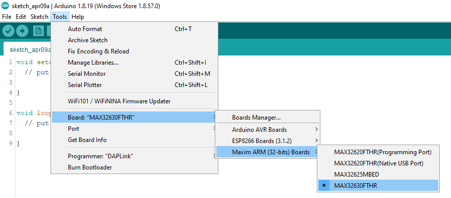
We are almost ready to flash the board, but if you are a Windows user and do not already have the mbed serial drivers installed, then you will need to download and install them from os.mbed.com/.../Windows-serial-configuration .
Hardware Setup
Now we need to plug things in. The MAX32630FTHR kit should come with a MAX32625PICO already set up as a DAPLink programmer. This needs to be plugged into the machine via USB and the MAX32630FTHR via the tiny ribbon cable, and the MAX32630FTHR needs to be powered via its USB socket. Even if you plug the MAX32630FTHR into the computer and a serial port shows up, you can not programme it directly. You will always need to use the MAX32625PICO.
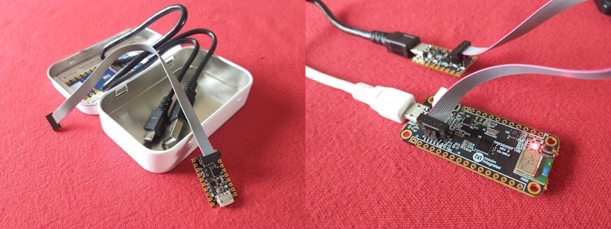
Now from the Tools menu we select the Port of the MAX32625PICO, set Programmer to “DAPLink”, and we are ready to go. Try flashing the good old Blink example and it should just work.
Fun fact, the binary is transferred by copying a file to the virtual drive. When this happens the drive vanishes, and then reappears, and your computer will do whatever it does when a flash drive is inserted. If it fails then just try a second time and it will often then work.
Random Notes
The Arduino Core is well rounded and most things work as they would with any other device. UART1 that can be used for debugging is accessed via Serial1, but that is also mapped to Serial for compatibility. The Bluetooth module is on UART0, but there is a little more work required to get that set up that I will document in the near future.
If you want a silly little sketch to make the LEDs flash then this is what you need. 
void setup() {
pinMode(P2_4, OUTPUT);
pinMode(P2_5, OUTPUT);
pinMode(P2_6, OUTPUT);
}

void loop() {
digitalWrite(P2_4, random(10)>5);
digitalWrite(P2_5, random(10)>5);
digitalWrite(P2_6, random(10)>5);
delay(250);
}
If you need to get advanced then much of the Maxim Microcontrollers SDK is included in the Arduino Core. I will be covering a bit about this when I document communicating with the Bluetooth module. Doing this is less Arduino development and more high end C++ development inside the Arduino IDE though. If you need to do a lot of that then another tool chanin may be more appropriate for your project.
Finally here are some useful things that I have been using while figuring this out…


