


In Part 3 of my Series, I will be sharing the Unboxing, and How i had setup my computer for the Programming.
Recap:
The idea is simple enough: stop making people swipe a card and type a PIN at every single door. Instead, the ID card (a MAX32630FTHR + ATECC508A in your pocket) unlocks once via PIN, then silently does challenge-response crypto over Bluetooth every time you walk up to a door. If the card gets yanked off you, the IMU detects the tug and it locks itself. No PIN, no entry. For more details check the Part 1 of the series
- Part 1 - The Idea Identity Protocol Part 1 - Plan
- Part 2 - Django Server - Identity Protocol - Part 2 - Django Server
The Unboxing
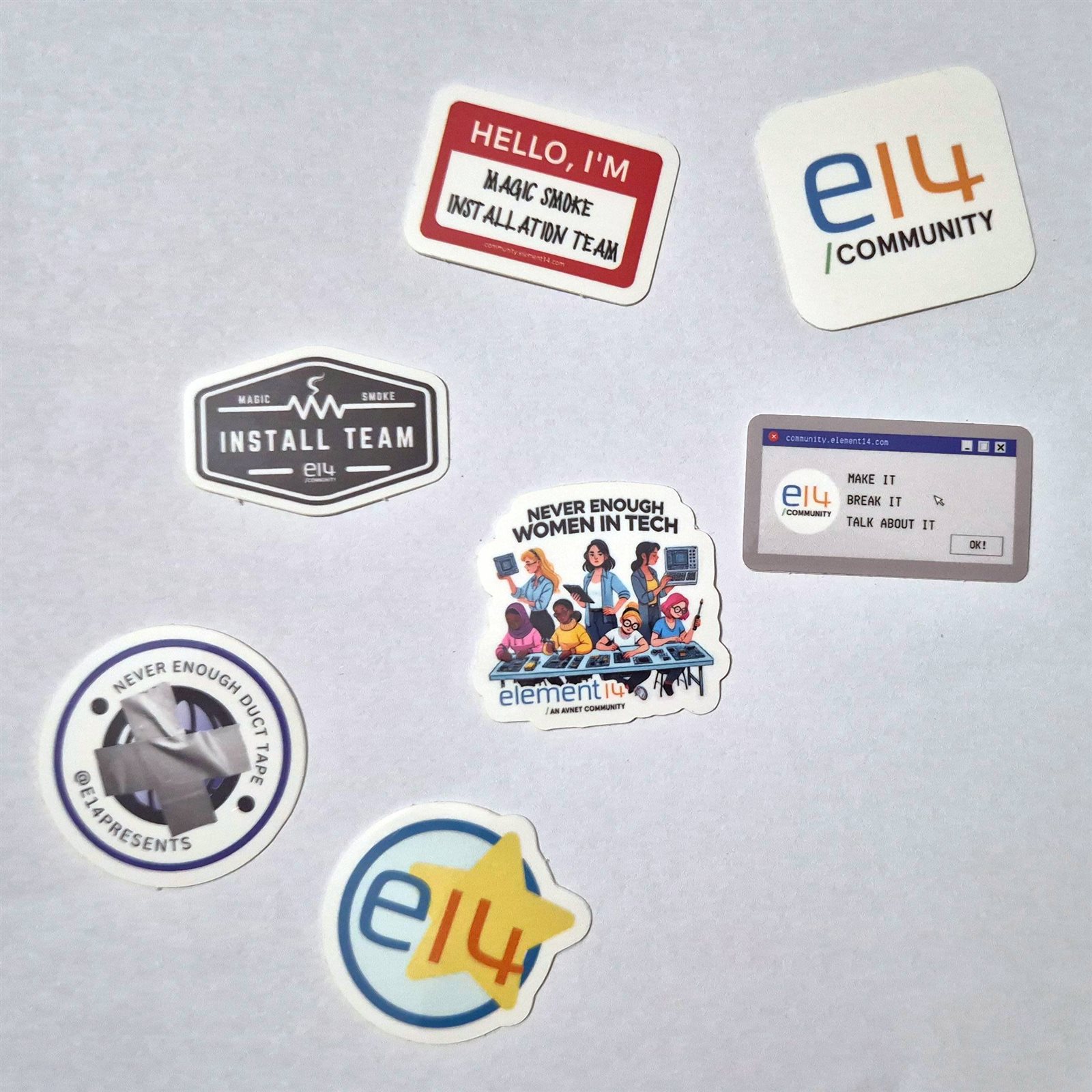
E14 always does a great job of packing ensuring that the products arrive safely. I looking at the sponsored kit, i expected the package size to be small but i was stunned to see quite a large one. As i opened and removed the packing material, came out confetti. Or was it? Nope, it was the Stickers, Yayyy. Stickers. I love sticking them to my electronics storage boxes for a cool effect.
Then the Striking Blue Box with Analog Devices Emblazoned on it. I thought this might be the Feather board because i thought Analog Devices had bought Maxim. But Inside i found the FTHR-PMD-INTZ Adapter Board. E14 did mention that they could ship only one out of the two they promised and they will ship the second one soon. But Since it is not going to be used in my project, I'm gonna say not to ship it to me, If anyone want's it. I can ask e14 to ship it to them instead (if they allow)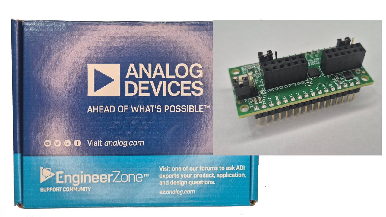
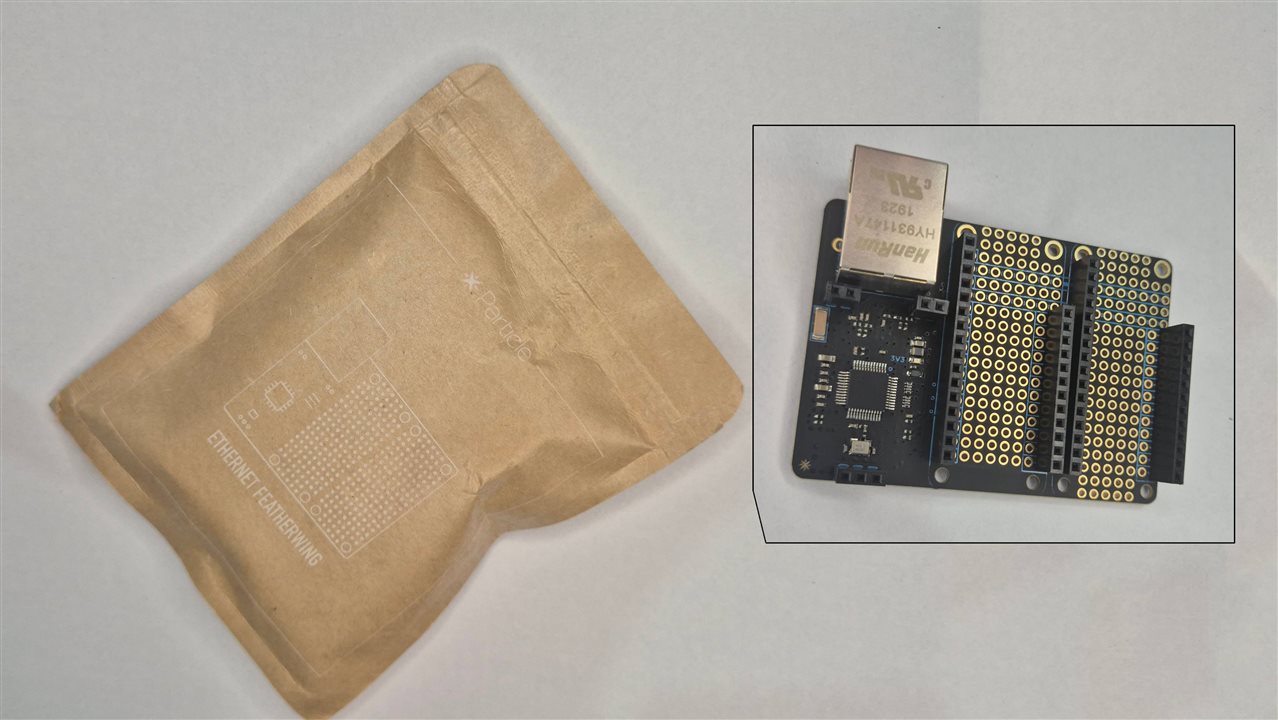
Then came the artisanal style packaging by Particle. Nestled inside the earthy paperish minimal packing was the Matte-Black gold plated PCB just shining there.
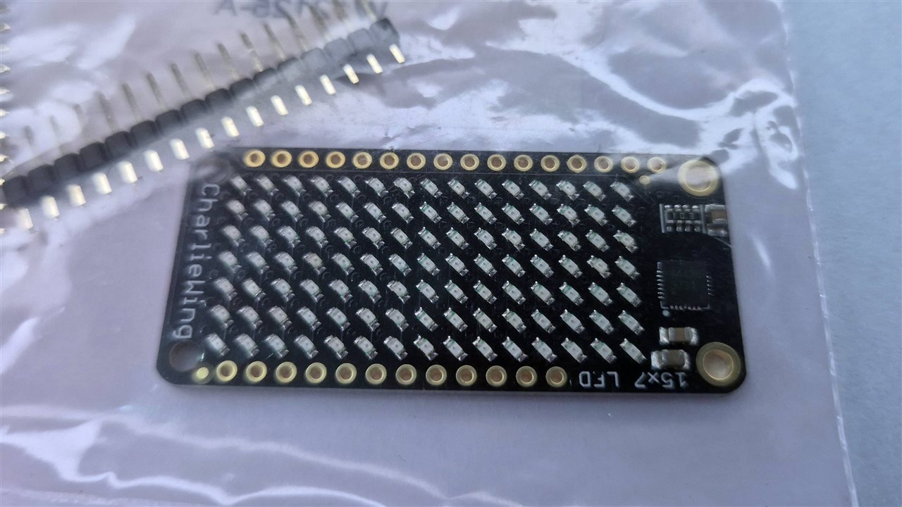
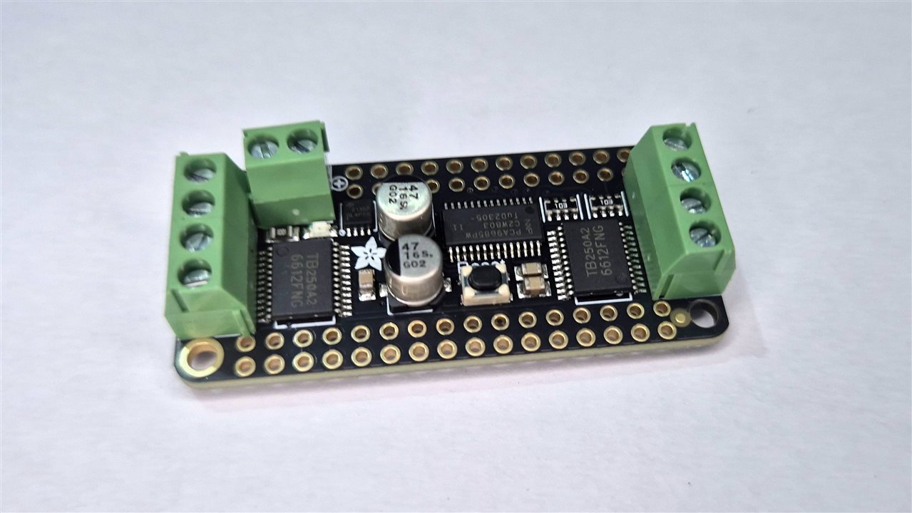
CharliePlex Featherwing and The Motor Control Wing in the Adafruit's classic transparent and Pink zip pouches respectively, The charlieplex LED was red. I would have liked it better with White, but hey it is classic.
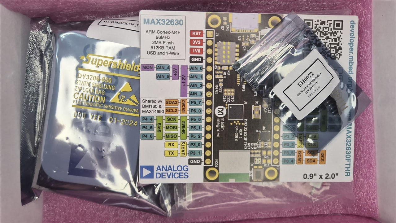
And them deep inside was two white unbranded boxes. Inside them were the power houses MAX63230 Feather Board. i Love them giving the pin out card. Helped me make a header file for the programming so easily and also for quick references.
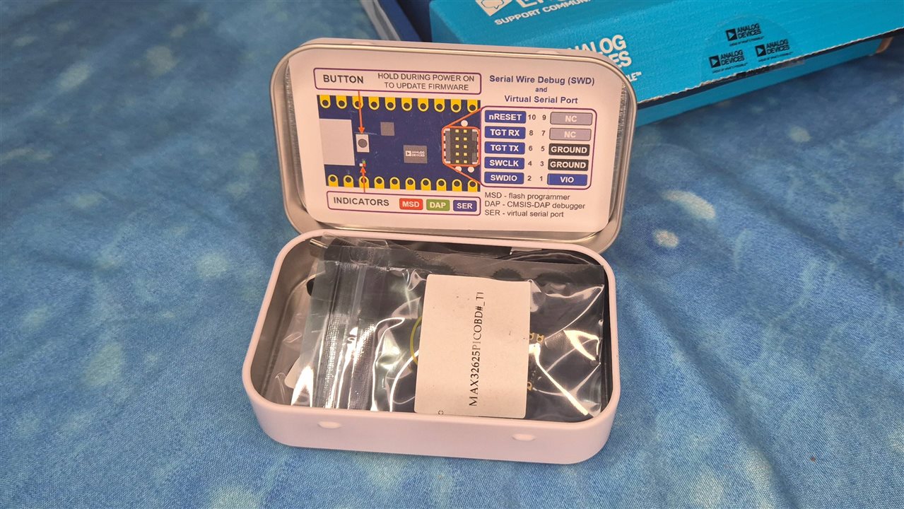
The Programmer was inside an Analog Devices Branded Altoid Tin style box. I would have liked it if not for the fact that there was no ESD padding in the inside. I am gonna reuse the pink one from the outer box. Inside was the Pico Programmer, A Micro USB Cable and the IDC - Ribbon Cable, Even the programmer comes with it's own Pinout card
and finally the Feather board itself.
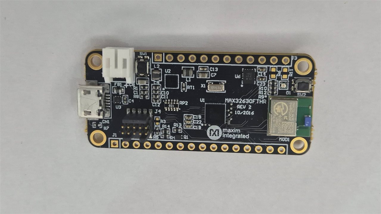
Setting up the SDK and IDE
Download the LPSDK File by going to https://www.analog.com/en/products/max32630.html and under "Tools & Simulations", Download the right SDK for your OS. No Linux option  Yes, You will need to login and then it will download all the files.
Install the LPSDK from here. Do set a path without spaces. I am setting it up at "D:\projects\electronics-libraries\maxim". You should be able to see a folder structure like this below

maxim/
├── Eclipse/          ← Eclipse IDE with Maxim CDT plugin
├── Firmware/
│   └── MAX3263X/
│       ├── Applications/
│       │   └── EvKitExamples/    ← ready-to-build example projects
│       └── Libraries/
│           ├── Boards/EvKit_V1/  ← board support (shared with FTHR)
│           ├── CMSIS/            ← ARM CMSIS + linker scripts
│           └── MAX3263XPeriphDriver/
├── Toolchain/
│   ├── bin/          ← arm-none-eabi-gcc, arm-none-eabi-gdb, …
│   └── msys/1.0/bin/ ← make, uname, mkdir, rm, …
└── setenv.bat        ← sets PATH for a cmd.exe session
You have the Eclipse project too. It was a straight forward option to open it, make a blinky compile and then upload it. But then It doesnt work. This is where i spent a lot of time. Now, The SDK ships board support for the EvKit_V1 evaluation kit. The MAX32630FTHR has similar peripherals but different pin connection. The default code is trying to initialize the board with the MAX14690N PMIC over I2CM0 but on the FTHR the PMIC is wired to I2CM2. The I2C transaction waits indefinitely for an ACK, so firmware never reaches `main()`. This happens regardless of whether you build from Eclipse or the command line. it's a firmware issue, not an IDE issue. I switched to command line to keep things simple, but Eclipse works fine too once you configure it as a Makefile project pointing at the LPSDK's own make.exe. So had to override Board_Init() as below
int Board_Init(void)
{
 return E_NO_ERROR;   /* skip EvKit PMIC init — PMIC is on I2CM2 on FTHR */
}
The BlinkY Code
#include "mxc_config.h"
#include "gpio.h"
#include "tmr_utils.h"

/*
 * Override the weak Board_Init() from EvKit_V1/board.c.
 * On the FTHR the PMIC is on I2CM2, not I2CM0 — the EvKit init hangs.
 */
int Board_Init(void)
{
    return E_NO_ERROR;
}

/* MAX32630FTHR RGB LED — active-low, open-drain */
#define LED_R_PORT  PORT_2
#define LED_R_PIN   PIN_4
#define LED_G_PORT  PORT_2
#define LED_G_PIN   PIN_5
#define LED_B_PORT  PORT_2
#define LED_B_PIN   PIN_6

static const gpio_cfg_t led_r = { LED_R_PORT, LED_R_PIN, GPIO_FUNC_GPIO, GPIO_PAD_OPEN_DRAIN };
static const gpio_cfg_t led_g = { LED_G_PORT, LED_G_PIN, GPIO_FUNC_GPIO, GPIO_PAD_OPEN_DRAIN };
static const gpio_cfg_t led_b = { LED_B_PORT, LED_B_PIN, GPIO_FUNC_GPIO, GPIO_PAD_OPEN_DRAIN };

static void leds_init(void)
{
    GPIO_Config(&led_r);
    GPIO_Config(&led_g);
    GPIO_Config(&led_b);
    /* all off — drive high (active-low) */
    GPIO_OutSet(&led_r);
    GPIO_OutSet(&led_g);
    GPIO_OutSet(&led_b);
}

int main(void)
{
    leds_init();

    while (1) {
        /* Red on */
        GPIO_OutClr(&led_r);
        TMR_Delay(MXC_TMR0, MSEC(500));
        GPIO_OutSet(&led_r);

        /* Green on */
        GPIO_OutClr(&led_g);
        TMR_Delay(MXC_TMR0, MSEC(500));
        GPIO_OutSet(&led_g);

        /* Blue on */
        GPIO_OutClr(&led_b);
        TMR_Delay(MXC_TMR0, MSEC(500));
        GPIO_OutSet(&led_b);
    }
}
The Makefile
PROJECT  = blinky
TARGET   = MAX3263X
COMPILER = GCC
BOARD    = EvKit_V1

# Hardcode TARGET_UC/TARGET_LC — $(shell tr ...) breaks in PowerShell outside MSYS
TARGET_UC := MAX3263X
TARGET_LC := max3263x

# Path to the LPSDK Firmware folder (adjust if your install path differs)
MAXIM_SDK = /d/projects/electronics-libraries/maxim/Firmware/MAX3263X

# Toolchain (bundled with LPSDK)
TOOL_DIR = /d/projects/electronics-libraries/maxim/Toolchain/bin

LIBS_DIR   = $(MAXIM_SDK)/Libraries
CMSIS_ROOT = $(LIBS_DIR)/CMSIS

# Sources
SRCS  = main.c
VPATH = src
IPATH = src

PROJ_CFLAGS += -DMXC_ASSERT_ENABLE

# Board support
BOARD_DIR = $(LIBS_DIR)/Boards/$(BOARD)
include $(BOARD_DIR)/board.mk

# Peripheral driver
PERIPH_DRIVER_DIR = $(LIBS_DIR)/$(TARGET_UC)PeriphDriver
include $(PERIPH_DRIVER_DIR)/periphdriver.mk

# CMSIS + linker rules (must be last include)
include $(CMSIS_ROOT)/Device/Maxim/$(TARGET_UC)/Source/$(COMPILER)/$(TARGET_LC).mk
Do update the path to the place where you installed the SDK. The LPSDK ships its own make.exe and MSYS utilities. You must use these, I had STM32 toolchain installed, and by default had it's path in the environment. It did not work out well. So i had to add the path manually by running a batch script for the MAXIM Project before i ran anything.
$lpsdk = "D:\projects\electronics-libraries\maxim"
$env:PATH = "$lpsdk\Toolchain\msys\1.0\bin;$lpsdk\Toolchain\bin;$env:PATH"
Flashing with OpenOCD
openocd -f interface/cmsis-dap.cfg
        -f target/max3263x.cfg
        -c "program build/blinky.elf verify reset exit"
Or you can drag and drop on the Disk drive that appears when you plug in the programmer.
Once i added printf to output to serial. it was producing no output at all even though the blinky was clearly running. Turns out the SDK routes printf through a UART and you have to tell it which one. On the FFeather, the DAPLink USB serial is on UART1 (pins P2_0/P2_1). Add this to your PROJ_CFLAGS in the Makefile:
PROJ_CFLAGS += -DCONSOLE_UART=1
A final note
This technique works with any IDE you prefer Visual Studio Code, CLion, Eclipse, whatever fits your workflow Now I am gonna be traveling to Goa for work next week. Hopefully i will get some free time to enjoy the beaches there, So If anyone has a doubt on setting up the toolchain, do comment and I'll try my best to respond back. Will also write a note on setting up the Debugger soon.


