element14 Community
element14 Community
    Register Log In
  • Site
  • Search
  • Log In Register
  • Community Hub
    Community Hub
    • What's New on element14
    • Feedback and Support
    • Benefits of Membership
    • Personal Blogs
    • Members Area
    • Achievement Levels
  • Learn
    Learn
    • Ask an Expert
    • eBooks
    • element14 presents
    • Learning Center
    • Tech Spotlight
    • STEM Academy
    • Webinars, Training and Events
    • Learning Groups
  • Technologies
    Technologies
    • 3D Printing
    • FPGA
    • Industrial Automation
    • Internet of Things
    • Power & Energy
    • Sensors
    • Technology Groups
  • Challenges & Projects
    Challenges & Projects
    • Design Challenges
    • element14 presents Projects
    • Project14
    • Arduino Projects
    • Raspberry Pi Projects
    • Project Groups
  • Products
    Products
    • Arduino
    • Avnet & Tria Boards Community
    • Dev Tools
    • Manufacturers
    • Multicomp Pro
    • Product Groups
    • Raspberry Pi
    • RoadTests & Reviews
  • About Us
    About the element14 Community
  • Store
    Store
    • Visit Your Store
    • Choose another store...
      • Europe
      •  Austria (German)
      •  Belgium (Dutch, French)
      •  Bulgaria (Bulgarian)
      •  Czech Republic (Czech)
      •  Denmark (Danish)
      •  Estonia (Estonian)
      •  Finland (Finnish)
      •  France (French)
      •  Germany (German)
      •  Hungary (Hungarian)
      •  Ireland
      •  Israel
      •  Italy (Italian)
      •  Latvia (Latvian)
      •  
      •  Lithuania (Lithuanian)
      •  Netherlands (Dutch)
      •  Norway (Norwegian)
      •  Poland (Polish)
      •  Portugal (Portuguese)
      •  Romania (Romanian)
      •  Russia (Russian)
      •  Slovakia (Slovak)
      •  Slovenia (Slovenian)
      •  Spain (Spanish)
      •  Sweden (Swedish)
      •  Switzerland(German, French)
      •  Turkey (Turkish)
      •  United Kingdom
      • Asia Pacific
      •  Australia
      •  China
      •  Hong Kong
      •  India
      •  Japan
      •  Korea (Korean)
      •  Malaysia
      •  New Zealand
      •  Philippines
      •  Singapore
      •  Taiwan
      •  Thailand (Thai)
      •  Vietnam
      • Americas
      •  Brazil (Portuguese)
      •  Canada
      •  Mexico (Spanish)
      •  United States
      Can't find the country/region you're looking for? Visit our export site or find a local distributor.
  • Translate
  • Profile
  • Settings
Smart Security and Surveillance
  • Challenges & Projects
  • Design Challenges
  • Smart Security and Surveillance
  • More
  • Cancel
Smart Security and Surveillance
Forum Accessing the PAN1326B Bluetooth module with the Arduino IDE (Don't Forget to Set)
  • News
  • Projects
  • Forum
  • DC
  • Leaderboard
  • Files
  • Members
  • More
  • Cancel
  • New
Join Smart Security and Surveillance to participate - click to join for free!
Actions
  • Share
  • More
  • Cancel
Forum Thread Details
  • Replies 3 replies
  • Subscribers 46 subscribers
  • Views 151 views
  • Users 0 members are here
Related

Accessing the PAN1326B Bluetooth module with the Arduino IDE (Don't Forget to Set)

Alistair
Alistair 26 days ago

Well that was a bit of a challenge, but I am now able to access the Bluetooth module on the MAX32630FTHR with the Arduino platform without hacking any of the core libraries. I honestly expected to be able to find a simple example online that I could work from, but one did not exist, so I have created that here.

The Arduino core for the MAX32630FTHR does not have any functionality built in for the PAN1326B, but it does expose the UART and the data pins, and includes the SDK for any other definitions we may (and will) need.

Before anything we need to include some SDK libraries with definitions for some flag addresses. I have seen many MAX3260 examples including many libraries that are just not needed or used, and all we need here are these two.

#include <pwrseq_regs.h>
#include <pwrman_regs.h>

The first thing I do is to pull the reset pin low (aka active) white we set up some other things. There is an obscure hardware bug in the module design that at times prevents the reset from functioning as it should later, so if we do this now it will insure the module is reset. I will cover more about this soon.

#define BT_RST P1_6
digitalWrite(BT_RST, LOW);

Next we need to change some low level settings in the microcontroller to enable a feature that puts the 32768Hz oscillator frequency on P1.7. The PAN1326B requires this frequency and this is a very convenient way of supplying that frequency without any extra hardware. A great design idea.

This is not built into the Arduino Core for the MAX32630FTHR, but the following command using definitions from the SDK will enable it.

MXC_PWRSEQ->reg4 |= MXC_F_PWRSEQ_REG4_PWR_PSEQ_32K_EN;

This also has a side effect of hijacking P1.6 (documented in the MAX32630 errata sheet), and you may have clocked that this is what we use for resetting the PAN1326B module. Luckily it is set to an input with a pullup so it will work most of the time. This does introduce issues with power cycling, but again I will come to that soon.

Now we need to set up the UART to communicate with the module. The module is hard wired with RX and TX on P0.0 and P0.1, with CTS on P0.2 and RTS P0.3 (documented on the schematic). The hardware supports hardware flow control, but the Arduino core does not. There is also an issue as the RX and TX lines are crossed when they should not be (or are not crossed when they should be, depending on your interpretation of RX and TX). I do not know if this was a mistake, or a simplification in layout that relies on software configuration, but the microcontroller allows the RX and TX lines to be inverted so all is good.

My approach was to keep things simple and use as much of the Arduino core as possible, and then go in after and change the required flags. There is little point changing any settings before using the Arduino command to initialise the UART as most settings will be overridden.

So here is what I do. First initialise the UART, that is UART0 on the microcontroller, that the Arduino core maps to Serial0. Then set the flags to enable the RTS/CTS hardware flow control, and swap the RX and TX lines.

Serial0.begin(115200);

MXC_IOMAN->uart0_req |= MXC_F_IOMAN_UART0_REQ_CTS_IO_REQ | MXC_F_IOMAN_UART0_REQ_RTS_IO_REQ | MXC_F_IOMAN_UART0_REQ_IO_MAP;

Remember, always change the settings after initialization or they will be lost.

Finally for the sake of completeness I then attempt to set the reset pin high to enable the module. Because of the aforementioned bug this makes little difference, but if this is ever changed in a future hardware update I would want my code to continue to work.

digitalWrite(BT_RST, HIGH);

Now a small issue that still remains is that sometimes the module will not start. After uploading the code it almost always starts fine. After a power cycle it is hit and miss, and often does not initialise. Physically resetting the module by pulling the MAX32630FTHR RST pin to GNG always appears to work. Using the SW1 (soft reset) button will continue to work if it did, and will not work if it did not when pressed (aka makes no difference). My assumption this is related to the 32KHz and P1.6 issue, as if so there is little I can do in code to address the issue. At least I can rely on the hardware reset.

To test we can send the HCI reset command to the module. We should get back 0x04, 0x0E, 0x04, 0x01, 0x03, 0x0C, 0x00 .

const char HCI_RESET_CMD[] = {0x01, 0x03, 0x0C, 0x00};
BT_SERIAL.write(HCI_RESET_CMD, sizeof(HCI_RESET_CMD));

And here is a complete test sketch…

#include <pwrseq_regs.h>
#include <pwrman_regs.h>

// PAN1326C2 HCI UART (use Serial on MAX32630FTHR)
#define BT_SERIAL Serial0
#define BT_RST P1_6

// Setup procedure
void setup() {
  // Open serial for debugging
  Serial.begin(115200);

  // Reset the PAN1326C2
  pinMode(BT_RST, OUTPUT);
  digitalWrite(BT_RST, LOW);

  // from 4.5.1.5.2 Enabling 32768Hz Oscillator Output on P1.7
  MXC_PWRSEQ->reg4 |= MXC_F_PWRSEQ_REG4_PWR_PSEQ_32K_EN;

  // Initialize HCI UART at default 115200
  BT_SERIAL.begin(115200);

  // Swap the RX/TX lines and enable CTS & RTS
  MXC_IOMAN->uart0_req |= MXC_F_IOMAN_UART0_REQ_CTS_IO_REQ | MXC_F_IOMAN_UART0_REQ_RTS_IO_REQ | MXC_F_IOMAN_UART0_REQ_IO_MAP;

  // Wait for initalisation 
  delay(200);
  
  // Enable the PAN1326C2 module
  digitalWrite(BT_RST, HIGH);

  Serial.println("Starting...");

  // Send the HCI reset command
  const char HCI_RESET_CMD[] = {0x01, 0x03, 0x0C, 0x00}; 
  BT_SERIAL.write(HCI_RESET_CMD, sizeof(HCI_RESET_CMD));
}

// The main loop
void loop() {
  if (BT_SERIAL.available()) {
    char data = BT_SERIAL.read();
    Serial.println(data, HEX);
  }
}

The solution was so simple. If only it was not such a journey to find it.

So I hope that is helpful. If anyone has any insight to the initialization issues then I would really love to know. If it can be fixed in software then that would make my life so much easier. Also I need to start talking HCI to the Bluetooth module. This should just be some donkey work, and I only need a few commands for my project, but I will look to see if there is an appropriate library I can use instead. Any recommendations are welcome.

  • Sign in to reply
  • Cancel

Top Replies

  • Alistair
    Alistair 26 days ago in reply to BigG +1
    Good spot in the voltage. Thanks. Truth is I clocked the module was 3.3v tolerant, and the Max reads 1.8v as high, so decided to not worry about it until later. Then I completely forgot about it. Yes I…
  • BigG
    BigG 26 days ago

    I concur. It is indeed a challenge. With Arduino you expect a decent enough SDK wrapper to shield you from all the nitty gritty. But once you work out how, it is fairly straight forward, as you say.

    I have a few comments.

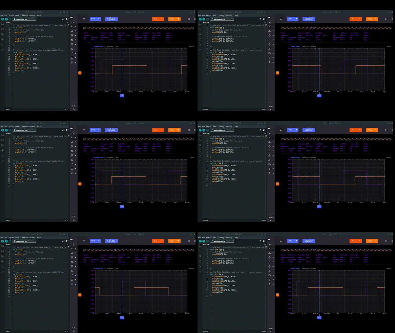
    I noticed that you have not set the pins to 1V8 for the Bluetooth module. Was this intentional? I used useVDDIO(pin_no) to set the BLE pins to 1V8 - alternatively, if you need to switch back you could use useVDDIOH(pin_no) for 3V3. In my opinion, this is one of the very cool unique features of the MAX32630 which is that you can individually define which pin is logic 1V8 versus 3V3. I tested this and it indeed works rather well (video for other readers).

    image

    I like the use of MXC_IOMAN->uart0_req |= MXC_F_IOMAN_UART0_REQ_CTS_IO_REQ | MXC_F_IOMAN_UART0_REQ_RTS_IO_REQ | MXC_F_IOMAN_UART0_REQ_IO_MAP;

    That is much easier to understand.

    Finally, great spot with the Errata. I had not seen that. Unfortunately we cannot monitor P1_6 with an oscilloscope. I would be interested to see what effect the P1_7 clock coupling has.

    • Cancel
    • Vote Up 0 Vote Down
    • Sign in to reply
    • Cancel
  • Alistair
    Alistair 26 days ago in reply to BigG

    Good spot in the voltage. Thanks. Truth is I clocked the module was 3.3v tolerant, and the Max reads 1.8v as high, so decided to not worry about it until later. Then I completely forgot about it. Yes I should and will use useVDDIO(pin_no), if for no other reason than to avoid issues if using the code on a less tolerant microcontroller.

    • Cancel
    • Vote Up +1 Vote Down
    • Sign in to reply
    • Cancel
  • Alistair
    Alistair 12 days ago

    A quick hack to work round the intermittent not initialising issue. In short I have tied a data pin that is normally floating to the reset pin, and if I do not detect any data from the module within 4 seconds I enable the pin and pull it low. I chase P3_0 as this is not used by default. I have a global variable hadResponce...

    int hadResponce = false;

    I then set that in my test read code...

    while (BT_SERIAL.available()) {
      uint8_t data = BT_SERIAL.read();
      Serial.println(data, HEX);
      hadResponce = true;
    }

    ...and finally in the main loop I check if it has not been set and if we have been running for 4 seconds.

      if (!hadResponce && (millis()>4000) ) {
        Serial.println("Stalled so rebooting...");
        delay(200);
        pinMode(P3_0, OUTPUT);
        digitalWrite(P3_0, LOW);
      }

    It is a complete hack and needs tidying, but it is automating things while I am testing so well worth doing.

    image

    • Cancel
    • Vote Up 0 Vote Down
    • Sign in to reply
    • Cancel
element14 Community

element14 is the first online community specifically for engineers. Connect with your peers and get expert answers to your questions.

  • Members
  • Learn
  • Technologies
  • Challenges & Projects
  • Products
  • Store
  • About Us
  • Feedback & Support
  • FAQs
  • Terms of Use
  • Privacy Policy
  • Legal and Copyright Notices
  • Sitemap
  • Cookies

An Avnet Company © 2026 Premier Farnell Limited. All Rights Reserved.

Premier Farnell Ltd, registered in England and Wales (no 00876412), registered office: Farnell House, Forge Lane, Leeds LS12 2NE.

ICP 备案号 10220084.

Follow element14

  • X
  • Facebook
  • linkedin
  • YouTube