

Bit late to get started, I know, but unavoidable given exams and travel commitments. Thankfully I’ve found myself with some free time and all the components I ordered have arrived so should be smooth sailing from now on (sarcasm).
This is my second post so I’ll start with a reminder of what my project is, walk through the components I’ve chosen for it, get into some specifics, then explain my action plan and potential challenges ahead.
The Project
My project is essentially a two-node autonomous security system. Node A includes a camera and stepper motor to pick up movement and follow a target. It also uses the board’s in-built IMU to detect when it is being tampered with. This data is then sent via Bluetooth to Node B – the ‘command station’. This receives the alert (movement or tampering), and outputs the relevant signal on the LED board. It should also log the incident to the main computer using a simple Python server.
The Components
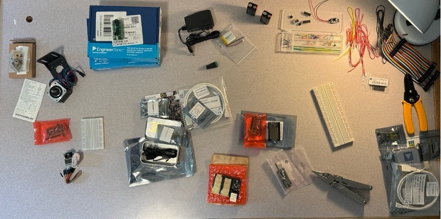
I was lucky enough to win the nomination and receive many components for free. My proposal was based around this and I try to incorporate as many elements of these as possible within my design. Others were ordered specifically for the project and I also take advantage of my existing inventory.
The motor
This is essential for my camera to pan and track targets. Otherwise it is just a stationary camera which is not very useful nor creative. I decided a NEMA 17 motor would be most useful for my project and ordered one along with a steel mounting bracket for stability. At least that was the intention and have since come to find the bracket may act more as dead weight than anything useful. Well at least it looks nice. I also ordered a 5mm coupling for the motor shaft, allowing me to directly mount components on top of the motor. Probably avoided in industry but works fine for this.
The stepper motor is driven with the included ADA2927 driver. Two are included but only one is needed. This is powered from a wall AC – 12V 1 A adapter, split into two terminals with a DC barrel jack – 2 pin connector. Slightly concerned by the 12W output but may be acceptable for a single NEMA 17 motor not needing much torque.
The camara (and rest of Node A)
I am using the Arducam Mini 2MP Plus OV2640. Should be able to suitably take power from our setup and send data to the Node A MAX32630FTHR#. The camera should provide suitable on-board compression to allow the board to process frame differences to detect movement and drive the motor. The IMU should also work to detect tampering (IMU triggering disabled during motor movement to eliminate false detections). Given unfortunate time constraints there won’t be SD storage. State information and times are sent to Node B via Bluetooth. States being “connection”, “movement” and “tampering”. No connection could display static or something on the LED matrix. This just makes it look more engaging than just having a single LED light up to imply a state. Data should be sent to the computer to log state and timing information. The board on A will be powered directly with a 3.7V lithium battery.
Node B
This is pretty straightforward. Just another board connected to an LED matrix display. Either the CharliePlex FeatherWing 7x15 or the Würth Elektronnik ICLED Featherwing. If feasible within time constraints the Ethernet adapter will also be included. Since this is intended as the ‘command station’ we can just power it using USB from the computer.
Other stuff
There are some other components included such as the FTHR-PMD-INTZ Adapter which is likely necessary. I also have a couple 9V batteries, breadboards, wires, jumper wires, wire strippers, and a Leatherman Wave (very useful) which will all be incorporated.
The Plan
Time is very limited for me but there’s no point jumping in trying to get to the final design immediately. I plan to build this up in stages and test parts individually before putting it all together.
I’ll first start by getting one of the boards to display patterns on the LED matrix. This shows I can get the board powered up properly and code running. Then I’ll try triggering this by a Bluetooth signal from the other board. Then I’ll set up Node A to control the motor to angle the camera. Perhaps the trickiest I’ll attempt to get the camera module feeding data to the board, have the board analyse the frames, and use the analysis to direct the camera towards movement. If by miracle this all works well then I should be able to integrate this all together in addition with the IMU detection.
Final Thoughts
I have a clear plan ahead now and am excited for the days to come. To be honest I am a little nervous about this not working out perfectly within the time constraints but I hope to have something running to demonstrate, even if it means some deviation from the original plan. I’ve worked on more complex stuff before though not in the same time constraints. Regardless, it will be a learning experience and I will be documenting the whole process. The free socks are also appreciated!


