

Table of contents
.png?sv=2016-05-31&sr=b&sig=Of14S3B62BkqblwwwXxpagmN3v8h9MqSGD05L8%2BLdTs%3D&se=2026-03-29T23%3A59%3A59Z&sp=r&_=rB8bIWjT2VJft77+MFRldQ==)
Abstract
The idea stemmed from a need for intelligent building automation—one that adapts to environmental changes while managing secure access. The goal was to combine adaptive monitoring and smart access control in a distributed architecture.
Project
Adaptive Environmental Monitoring and Smart Access Control
Implementation: From Idea to Realization Using NXP FRDM MCX A & MCX N Development Kits
The Adaptive Environmental Monitoring and Smart Access Control project is an intelligent building automation solution designed around a distributed architecture using the NXP FRDM MCX A153 as the central hub and multiple FRDM MCX N236 boards as edge sensor nodes.
Potentially the Edge Nodes could integrate a range of environmental sensors—covering temperature, humidity, air quality, computer vision and motion—to monitor conditions throughout different building zones.And Potentially the Central Hub could feature adaptive algorithms that not only automate HVAC, lighting, and security functions, but also optimize energy use and provide secure, automated access control.
The project implements over-the-air (OTA) communication between the Central Hub and Edge Nodes, with candidate technologies—including LoRa, Bluetooth Low Energy (BLE), WiFi, and LTE—to be evaluated in order to determine the most efficient and reliable approach. This communication framework enables the seamless exchange of descriptive message data between the Hub and Edge Nodes. Additionally, OTA connectivity provides advanced capabilities for remote monitoring and real-time system control. Initially the Hub and and Edge Node will communicate over UART to test the flow of data between the two nodes.
Each phase, from initial unboxing and board inspection to sensor calibration and full system integration, is meticulously detailed to serve as a step-by-step guide, supporting smooth implementation and troubleshooting. Ultimately, this project demonstrates how combining versatile hardware platforms with adaptive software logic and connectivity yields scalable, secure, and efficient smart building solutions capable of real-time environmental monitoring and intelligent access management.
Comparison: NXP FRDM MCX A153 vs. NXP FRDM MCX N236 Development Kits
To justify the selection of which kit to use for the Central hub and the Edge nodes, I conducted a comparison of the two kits. The Similarities, Differences, Built in Sensors, Pins, Expansion, and development Environment are compared in this section.
Similarities
|
Feature |
FRDM MCX A153 |
FRDM MCX N236 |
|
MCU Architecture |
Arm Cortex-M33 up to 96 MHz |
Arm Cortex-M33, up to 150 MHz |
|
Built in WIFI |
NONE |
NONE |
|
Debug Capability |
MCU-Link onboard debugger |
MCU-Link onboard debugger |
|
Expansion Connectors |
Arduino UNO R3 headers, mikroBUS |
Arduino UNO R3 headers, mikroBUS |
|
User Interaction |
Push buttons, RGB/power LEDs |
Push buttons, RGB/power LEDs |
|
Communication Protocols |
I2C, SPI, UART |
I2C, SPI, UART |
|
Development Environment |
MCUXpresso IDE |
MCUXpresso IDE |
|
Power Supply |
USB Type-C connectors |
USB Type-C connectors |
|
Connectivity Types |
USB Type-C connectors |
USB Type-C connectors |
Both kits are designed for rapid prototyping, use the same IDE/software tools, support rich peripheral expansion, and offer plug-and-play sensor integration.
Differences
|
Feature |
FRDM MCX A153 |
FRDM MCX N236 |
|
Physical Size |
More compact |
Larger, with more densely packed features |
|
MCU Model |
MCX A153VLH |
MCXN236VDFT (TrustZone security enabled) |
|
Clock Speed |
up to 96 MHz |
faster processing capability & better performance up to 150 MHz |
|
Onboard Sensors |
None built-in |
3-axis accelerometer, visible light sensor, digital microphone |
|
Flash Memory |
Internal only |
+ 64Mbit QSPI flash onboard |
|
CAN Bus Support |
No |
Yes, with onboard CAN transceiver (TJA1057) |
|
Multimedia Hardware |
No direct support |
LCD (FlexIO), camera interface |
|
Developed Use Cases |
Low-power industrial, secure IoT hub |
Sensor-rich IoT and AI edge applications |
Sensors
- FRDM MCX A153:
No built-in sensors; relies on expansion via Arduino sockets, mikroBUS, or Pmod for external sensors (environmental, motion, etc.). - FRDM MCX N236:
Built-in 3-axis FXLS8974CFR3 accelerometer, visible light sensor, digital microphone, and supports sensor add-ons via headers.
Pins & Expansion
Both boards offer:
- 4x Arduino UNO R3-compatible sockets/headers for shields
- 2x mikroBUS sockets/headers for click modules
- 1x Pmod header for Digilent Pmod peripherals
- MCX N236 adds:
- FlexIO header for LCD
- Camera header for image applications
- Dedicated CAN header
Development Environment
- MCUXpresso IDE is used by both boards for firmware development, debugging, and demo application deployment.
- Both boards are detected via MCU-Link CMSIS-DAP interface.
- SDK examples and board support files are available for each.
Conclusion
Based on these comparisons:
I choose the MCX N236 as the Edge node for it's added support for Built-in sensors, FlexIO header for LCD,
Camera header for image applications, Dedicated CAN header and 64Mbit QSPI flash.
The MCX N236 was picked a the central hub for it's lack of features, which are not required in a central hub. If need be the mikroBUS or PMOD headers could be used to attach sensors.
Basic Design
This section gives a basic design for the architecture of the system. The main points are:
- Central Hub: deploy the NXP FRDM MCX A153 board for serving as the main coordinator.
- Edge Nodes: Deploy NXP FRDM MCX N236 boards in various building zones to interface with environmental sensors.
- System Layout: The edge nodes monitor local conditions and relay data to the central hub, which aggregates and acts on this information.
- Connectivity: initial connect the devices using UART. Then design an over the air solution once connectivity between the nodes is tested and proves to be working.
- Sensors & Control: Choose sensors for temperature, humidity, motion, and air quality; include relays for lighting and HVAC.
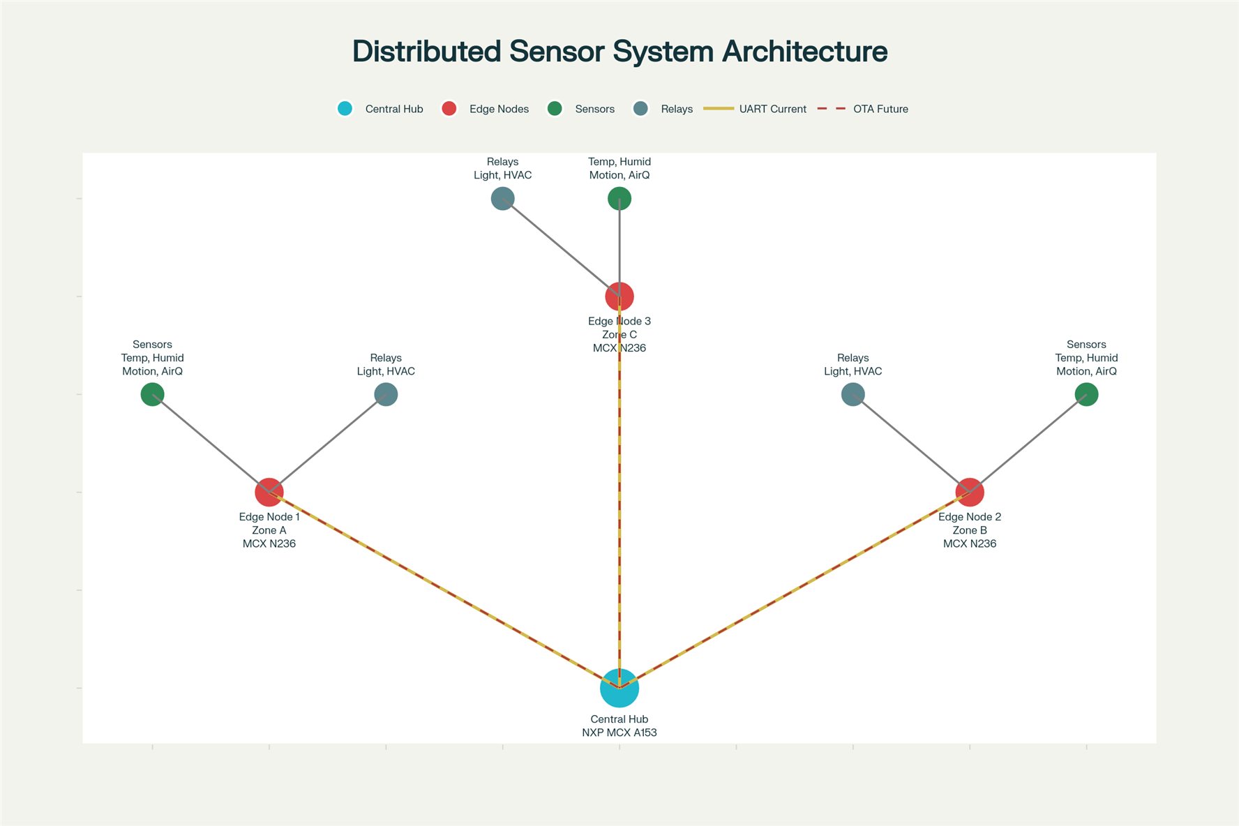
Here is a flow diagram representing the sensor system architecture as described, featuring NXP FRDM MCX A153 as the central hub and FRDM MCX N236 edge nodes. It visualizes edge zones interfacing with sensors (temperature, humidity, motion, air quality) and relays, initial UART connectivity, and the path for future wireless upgrades.
Getting to Know the MCX A153 (hub) and MCX N236 (edge node) boards
Unbox the Kits
- Unpack both MCX A153 (hub) and MCX N236 (edge node) boards.
- Check for all necessary cables, Quick Start Guides, and accessories.
- MCX A153
- USB Cable
- Guide
- MCX N236
- USB Cable
- Guide
- Jumper
- MCX A153
Inspect the Boards
- Carefully look for any bent pins or loose components.
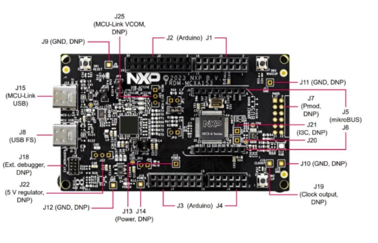
- Identify expansion headers for sensors: Arduino R3, mikroBUS, Pmod on MCX A153 (hub)
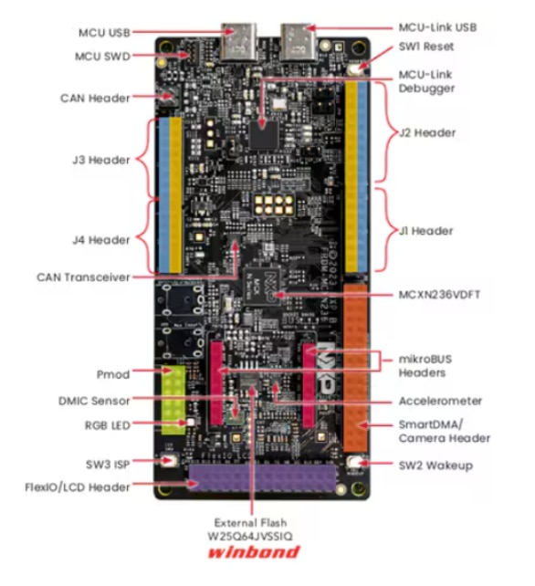
- Identify the Built-in sensor connectors, FlexIO header for LCD,
Camera header for image applications, Dedicated CAN header and 64Mbit QSPI flash on the MCX N236 (edge node) - MCX A153 (hub)
- MCX N236 (edge node)
Setup the Development Environment
My experience setting up the board development environment involved three key steps: Connecting to Power (plugging in cables, checking LEDs, and confirming PC recognition), Installing Development Software (downloading and installing MCUXpresso IDE and board SDK support packages), and Verifying Board Communication (checking board detection in the MCUXpresso IDE and flashing a demo program). The following sections will describe my journey.
Connect each Board to a PC .Plug In the Board for the:
MCXA153
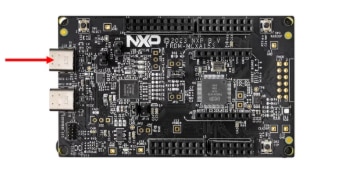
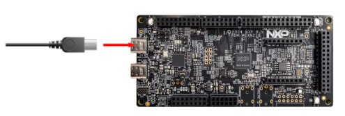
Power the board via a type-C USB cable from J15 to a PC or power supply, as shown below. The RGB LED should then blink steadily.
MCXN236
To power the board and run the demo program, connect a type-C USB cable from connector J10 to a host computer or power supply, as shown below The RGB LED should then blink steadily.
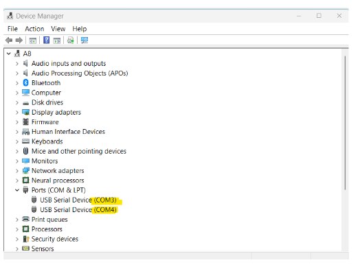
Showing 2 devices connected to my PC

Verify power LEDs
MCXA153
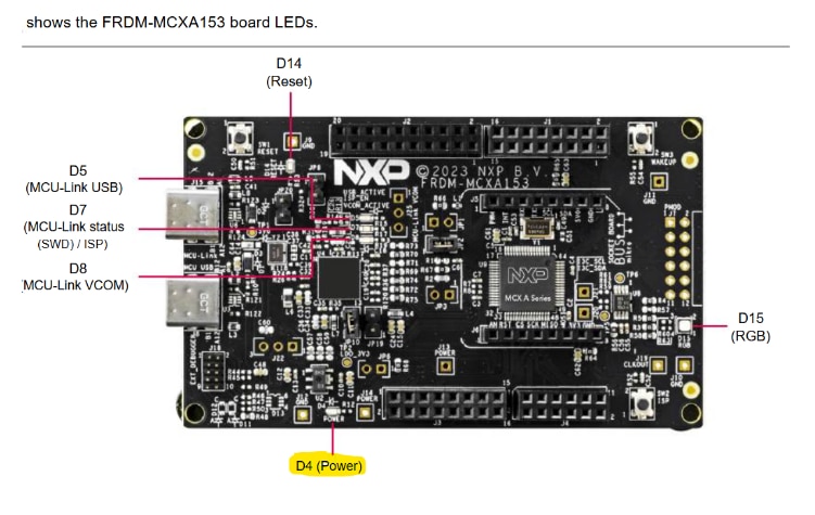
The power LED on the NXP FRDM-MCXA153 development board is labeled as "D4 (Power)"
The power LED is typically green and lights up solid when the board receives power through the USB Type-C connector or other power sources.
MCXN236
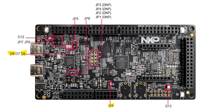
The power LED on the NXP FRDM-MCXN236 development board is labeled as "D3" and is green. It lights up solid when 3.3V power (LDO_3V3 supply) is available on the board, indicating the board is powered correctly.
DEBUG INTERFACE RECOGNITION
MCXA153 - COM3 :The D8(MCU-Link VCOM) LED (shown above) is a solid GREEN, while the D7(MCU-Link Status) LED is blinking slowly RED. For the Out Of the box demo program LED D15 RGB is blinking
MCXN236 - COM4: The MCU-Link VCOM interface on the FRDM-MCXN236 board is associated with dedicated status LEDs labeled as D8 (red), D6 (green), and D7 (blue). These three LEDs indicate various operational states of the onboard MCU-Link debug/VCOM probe. Specifically, D6 (green) will light up to show active VCOM (virtual COM port) activity, such as when the board is connected and exchanging serial data via the MCU-Link VCOM port. If the VCOM is actively transmitting or receiving, D8 may blink to reflect data transfer, while the other LEDs (D8 red and D7 blue) are used to indicate additional debug status or other probe operations.
For the Out Of the box demo program LED D13 RGB is blinking
The device manager shows the two com ports being used:
After hardware setup, development software was installed and configured. Initial development involved flashing basic test programs to verify communication and environment-hardware interfacing. Significant time was then spent learning to create code examples for each device, establishing a foundational understanding of software architectures for future development.The next sections describe my path.
Install MCUXpresso IDE and necessary board support packages/drivers.
Follow the instructions on the MCXA153 Software Page for the MCXA153 install. Then, follow the instructions on the MCXN236 Software Page for the MCXN236 install. They are pretty much the same for the IDE install, but have slight differences for each board. Basically, these guides help users set up and start developing with the MCXA153 and MCXN236 development boards. It covers installing necessary software, building and running projects, and using MCUXpresso’s developer tools. You will only need to install IDE once, since the IDE allows you to specify which board you are coding for. However, you must install the specific SDK for each board.
The document recommends multiple software packages suited for embedded system development, project configuration, programming, and provisioning NXP MCUs.
Software Installs
1. MCUXpresso IDE
Primary integrated development environment for NXP MCUs. Version 11.8.1 or above recommended.
I installed the latest version 25.6. Also installed were various J-Link Debuggers.. I’m wondering why?
This is what device manager now looks like after the install:

The com ports show that MCU-Link VCom is now used for the debugger ports
MCUXpresso for Visual Studio Code (Optional) is also available. I did not install this at this moment, but might check it out later,since I like coding in VS Code. It includes an extension for using MCUXpresso SDK features inside VS Code.
MCUXpresso SDK
Open-source software development kit providing drivers, board support packages, and source code.
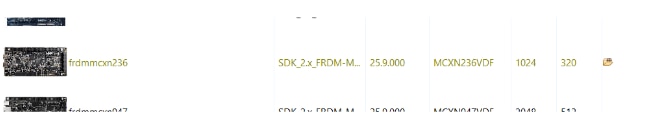
NOTE you will need to install the SDK for each device. Select the following from the SDK install. I installed the SDKs from the IDE using the instructions in the video on the Get Software Page.. Look for the Folder icon on the “Installed SDKs” Panel.
MCXA153

MCXN236
In the IDE “installed SDKs”” you should now see the following:
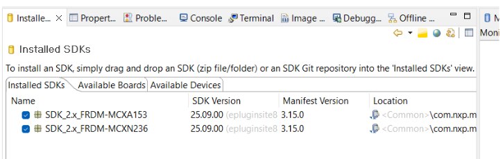
You will be selecting the SDK for the device you are coding on. This also contains example code for the board you're currently using. More on this later.
MCUXpresso Config Tools
Suite of tools for board configuration, including pin and clock setup and code generation. I installed this from the link in the Get Software Page.
MCUXpresso Secure Provisioning Tool (SEC Tool)
A GUI application for secure programming and provisioning of NXP MCUs.
I installed this from the link in the Get Software Page.
Each tool is linked on the page for download and more information. The SEC Tool helps with secure provisioning and mass production programming workflows. MCUXpresso SDK, IDE, and Config Tools together cover most development and device setup needs for the FRDM-MCXA153 & FRDM-MCXN236 boards. Now that you have a development environment setup, you can start coding. You’ll do this next
Flash basic test applications (e.g., LED blink, Hello World) to confirm setup.
Follow the instructions on the MCXA153 Build and Run Page for the MCXA153 board. Then, follow the instructions on the MCXN236 Software Page for the MCXN236. They follow the same format but have slight differences for each board.
On this page you'll learn:
- To import an SDK example (like hello_world) into MCUXpresso IDE.
- The guide walks you through selecting the FRDM MCX board, expanding the demo_apps category, and choosing hello_world.
- You’ll build the demo and set the debug console to UART for serial output.
- Steps include connecting the board via USB MCU-LINK port, flashing the application, and selecting the MCU-Link CMSIS-DAP debug probe. NOTE – Be sure to include the Instructions for opening a serial terminal (settings: 115200 baud, 8 data bits, no parity, 1 stop bit) are provided. Also, make sure you select the right Serial port (COM4 because my MCXN236 is connected to it ) for the device. You'll need to open a new terminal session to have this dialog come up. I made the mistake of using the terminal fro a previous run on the MCXA153, and there was no output displayrd.
- Finally, you will run the demo and see terminal output.
By completing the instructions on each device page , you will understand how to build, flash, and run sample applications on both NXP devices using MCUXpresso IDE or other supported toolchains, and how to monitor output through a UART serial connection.
I tried the “hello world example” on both devices to get a feel for developing on two devices from the same IDE on the same PC. I followed the instructions from the “Build and Run Page” outlined above.
Create a code example
Section Conclusion before going further you can skip if you see fit.
The only section I was able to complete was section 4.1. All the other sections had documentation errors. As I described above. But I get the general idea on using the IDE.
I was unable to complete Section 4.2 able to clone, configure, and enhance example LED projects. But since I will not be using 3rd party IDEs, I
I was also NOT able to finish section 4.3 and 4.4 on Pins configuration, manipulate pin routing, extend code capabilities, and visualize changes with additional output hardware, due to errors between the page content and the actual code in the SDK examples. So save you time and review these sections and if you can figure out the differences to see if you figure it out.
MCXA153 Create Page
Follow the instructions on the MCXA153 Create Page for the MCXA153 board.

Here’s what you can learn from Create Page:
- How to clone and modify SDK example projects:
- In section 4.1 Clone an Example Project from MCUXpresso IDE :
- You’ll import and run the ctimer_match_interrupt_example—a demo that sets up a PWM signal to switch between RED and GREEN LEDs using the CTimer peripheral.
- You’ll learn how to select the UART debug console to observe output.
- In section 4.1 Clone an Example Project from MCUXpresso IDE :
- Using MCUXpresso Config Tool for third-party IDEs:
- In section 4.2 Clone an Example Project Using MCUXpresso Config Tool for 3rd Party IDE
- Instructions are provided for cloning example projects using MCUXpresso Config Tool, supporting environments like IAR, KEIL, or Visual Studio Code.
- You’ll practice importing, compiling, and running LED output projects across different IDEs.
- In section 4.2 Clone an Example Project Using MCUXpresso Config Tool for 3rd Party IDE
- Working with Pins Tool in MCUXpresso IDE:
- In Section 4.3 Use MCUXpresso IDE Pins Tool
- You’ll learn how to use the IDE’s Pins Tool to view and edit pin routing, specifically for the ctimer project. In
- Section 4.4 Use the Pins Tools to Modify the LED Routed Pin:
- You’ll learn how to Modify routed pins to enable more LEDs:
- Step-by-step directions show you how to enable and configure additional pins (e.g., for the BLUE LED), making changes in the Pins Tool and updating your project code.
- You’ll export modified pin configuration files, add macros to initialize and control more LEDs, and ensure the GPIO peripheral is reset for new output.
- You’ll learn how to Modify routed pins to enable more LEDs:
- PROBLEMS IN DOCUMENTATION
- In section 4.4 steps 7 and 8
- Step 7 does not have the defines in the simple_match_interrupt.c
- Step 8 Does not have the Code specified and the arrow pointing to the code has an unreadable Argument and I’m not sure where to place the code in the main function.
- In section 4.4 steps 7 and 8
- Building and running after modifications.
- The guide has you build and flash the updated firmware, resulting in the board blinking GREEN and BLUE LEDs back and forth.
- I was never able to get the code running, so I could not verify this statement.
- In Section 4.3 Use MCUXpresso IDE Pins Tool
By completing this page, you’ll learn how to clone, configure, and enhance example LED projects on FRDM-MCXA153, manipulate pin routing, extend code capabilities, and visualize changes with additional output hardware. The approach is the same for the MCXN236. But be aware of the documentation error in the Config tool and the difference between the page and the SDK code examples for both device pages.
MCUXpresso Developer Experience
If you're interested in videos in addition to the other pages I described, this page is an excellent learning resource.
MCXA153 Page Link I learned how to set up the FRDM-MCXA153, leverage its expandability through shields, efficiently locate and use software code examples from NXP’s Application Code Hub, and utilize MCUXpresso for a streamlined developer experience, especially as demonstrated through hands-on demos with sample projects
MCXN2367 Page Link
I learned how to set up the FRDM-MCXN236 for embedded prototyping, leverage the MCUXpresso development environment to access code and drivers, and quickly expand system capabilities using ready-made modules and shields—giving you a streamlined path from hardware assembly to demo project implementation. With these sections completed hardware setup, and initial firmware verification, and learning about the MCUXpresso IDE. Now it's time to start developing my idea in the MCUXpresso IDE. Having prepared my hardware and environment, I’m ready to move to code development and system integration.
NEXT it's on to understanding on board sensors and UART usage
Sensor & UART Integration and Testing
This section will detail the use of the MCX N236's built-in sensors (temperature, motion, and light) and the UART on both the MCXN236 and MCXA153. It will cover utilizing the Sensor and UART demo projects in MCUXpresso IDE for data reading/writing and operational verification, as well as troubleshooting wiring and initialization.
Use built in sensors (temperature, motion, light) on the MCX N236. Use Sensor demo projects in MCUXpresso IDE to read sensor data, verify proper operation.
Use UART demo projects in MCUXpresso IDE to read/write over UART to/from the MCXN236/MCXA153 , verify proper operation.
For each demo, Troubleshoot wiring and initialization as needed.
Test built in Sensors on MCX N236 (edge node)
Use NXP’s demo applications to read sensor outputs within the IDE. writing data to the terminal.
I searched for an example for temp, light ,and accelerometer.
There is NO onboard sensor for temperature. You’ll need to connect one MIKEO etc, there is an MCU temperature example {Lpadc_temperature_measurement} where you can get the temp of the MCU. SO I used that as an example The next section describes my finding. I did run into some problems with the Debug Probe, which was very frustrating.
Using the SDK Example: Lpadc_temperature_measurement
The lpadc_temperature_measurement demo in the FRDM-MCXN236 SDK reads the internal temperature sensor of the MCXN236 MCU itself—not an external sensor on the board.
This demo uses the MCU's built-in bandgap-based temperature sensor, which is accessible via the LPADC (Low Power ADC) peripheral. The temperature value is sampled directly from inside the microcontroller, allowing you to monitor the chip’s junction/ambient temperature (useful for diagnostics, calibration, and MCU health monitoring).
- The reading comes from the MCXN236's internal temperature sensor, as measured by the LPADC peripheral.
- It does not use an external temperature sensor or a sensor mounted on the development board.
If you want to measure ambient temperature with an external sensor, you'd need to connect a separate sensor (such as DHT11/DHT22, LM75, etc.) or use one of the board headers for expansion.
Details
The lpadc_temperature_measurement example shows how to measure the temperature within the internal sensor. In this example, the ADC input channel is mapped to an internal temperature sensor. When running the project, typing any key into the debug console would trigger the conversion. ADC watermark interrupt would be asserted once the number of data words stored in the ADC Result FIFO is greater than watermark value. In ADC ISR, the watermark flag would be cleared by reading the conversion result value. When the conversion is done, two valid results will be put in the FIFO, then the temperature can be calculated within the two results and a specific formula.
Hardware requirements
- - Type-C USB cable
- - FRDM-MCXN236 board
- - Personal Computer
Build/Debug
- Import SDK example lpadc_temperature_measurement
- Select in the driver_examples/lpadc as shown below
- Build the example OK
- DEBUG/RUN OK
Prepare the Demo
- Connect a USB cable between the host PC and the EVK board J10.
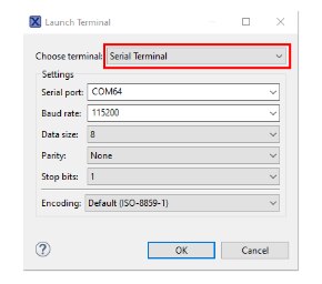
- Open a serial terminal with the following settings:
- - 115200 baud rate
- - 8 data bits
- - No parity
- - One stop bit
- - No flow control
- Download the program to the target board.
- Either press the reset button on your board or launch the debugger in your IDE to begin running the demo.
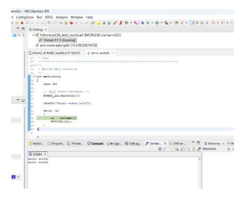
Running the demo
The log below shows the output of the hello world demo in the terminal window:
~~~~~~~~~~~~~~~~~~~~~~~~~~~~~~~~~~
LPADC Temperature Measurement Example
ADC Full Range: 65536
Please press any key to get temperature from the internal temperature sensor.
Current temperature: 22.319
Current temperature: 22.319
Current temperature: 22.707
Current temperature: 22.707
~~~~~~~~~~~~~~~~~~~~~~~~~~~~~~~~~~~
Now every thing is working I didn't get any screenshots but I assure you that I got it working on the MCXN236 . now I'd like to get the temperature readings in Fahrenheit. The next section describes how to modify the program to accomplish this.
At this point I was receiving the following error when I tried to debug on my MCXN236:
Ee(42). Could not connect to core. and No connection to the chip's debug port.
I eventually figured it out and was able to continue with this project If you get this error , refer to this forum link NO connection to chips debug port on the MCXN236: for details.
Convert Celsius to Fahrenheit
To convert 22.7°C to Fahrenheit use this formula:
Fahrenheit = 1.8. * Celsius + 32
Change output to Fahrenheit
follow the following instructions to make changes to the program
- Locate where the temperature value is calculated
- In the main code file lpadc_temperature_measurement.c there is an interrupt function DEMO_LPADC_IRQ_HANDLER_FUNC(void).
- After the line
g_CurrentTemperature = DEMO_MeasureTemperature(DEMO_LPADC_BASE, DEMO_LPADC_USER_CMDID, 0U);
-
- ADD the conversion to modify the global variable g_CurrentTemperature
// Convert Celsius to Fahrenheit
float F = 0.0f;
float C = g_CurrentTemperature;
g_CurrentTemperature = 1.8f * C + 32;
- ADD the conversion to modify the global variable g_CurrentTemperature
Follow the steps above to build, debug the project and run it
Conclusion
Results of the run showing temperature in farinheight. you have now modified your first example. I will use this program in my implementation.
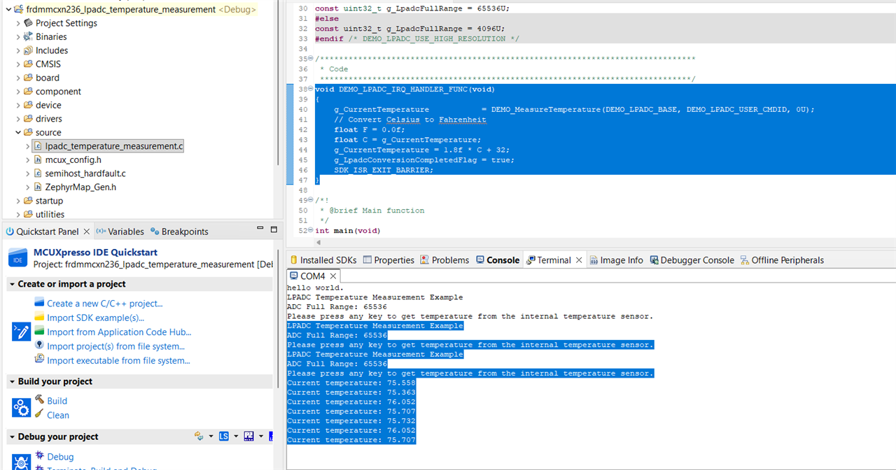
LPADC Temperature Measurement Example
ADC Full Range: 65536
Please press any key to get temperature from the internal temperature sensor.
Current temperature: 75.558
Current temperature: 75.363
Current temperature: 76.052
Current temperature: 75.707
Current temperature: 75.732
Current temperature: 76.052
Current temperature: 75.707
Current temperature: 76.126
TODO next
Test a UART connection between the N236 & A153
Connect the UART via USB cable or pins on each device
Write a test program that will send and receive messages between both.
SDK example found : lpuart_polling
Example also on challenger site: https://community.element14.com/challenges-projects/design-challenges/smart-spaces-design-challenge/f/forum/56339/dds-elevator---hello-world?ReplySortBy=CreatedDate&ReplySortOrder=Descending
PSDO CODE
The program contains 2 shareable functions Send and Receive.
The SEND() will send a message
The REVEIVE() will get the message and display it on the terminal screen.
On the MCX N236 (edge node)
Send a message or the value of a sensor.
On the MCX A153 (hub)
Receive the message
System Communication Test
Wired test: Connect MCX N node to MCX A hub via UART as planned. Flash demo code where sensor data is forwarded from N to A and printed via A’s UART.
Node recognition: Confirm that MCX A parses distinct node IDs and logs received values to terminal or onboard LCD.
Network expansion (optional): Attach additional MCX N boards to simulate multi-zone coverage. Confirm unique data from each node.
Step-by-Step Implementation
This is a detailed, step-by-step guide for bringing the distributed building automation system online using the NXP FRDM MCX A153 (hub) and MCX N236 (edge node) development kits. Taking what we have learnt in the section above titled "Getting to Know the MCX A153 (hub) and MCX N236 (edge node) boards", you now should have a working development environment to be able to write code for the MCX A and the MCX N. In this implementation you will use the built in sensors of the MCX N and process that sensor data on the MCX A. You will add features to the code and test the code.
1. Plan Network Architecture
- Deploy MCX A as the central hub, aggregating sensor data from MCX N nodes.
- Deploy MCX N as a edge node.
- Define message payloads for various sensor info, edge node ID etc. for data movement between hub and edge nodes.
2. Begin Integration
- Add the UART test code for sending and receiving messages.
- Start basic coding your building automation logic;
- MCX A manages central control
- display temp and ight messages
- Edge MCX N boards handle local sensor data and respond to events.
- send temp and light messages.
- MCX A manages central control
- Code Listed
- MXC N
- Read sensor data (e.g., temperature, light) and send via UART.
// MCX N236 Edge Node
// This example reads temperature and light data
// (replace get_temperature()/get_light() with your sensor SDK functions),
// then sends a message over UART.


#include "fsl_uart.h"
#include "board.h"

int get_temperature() {
    // Replace with actual sensor code
    return 23; // Demo value
}

int get_light() {
    // Replace with actual sensor code
    return 120; // Demo value
}

void send_sensor_data(void) {
    char message[64];
    int temp = get_temperature();
    int light = get_light();
    snprintf(message, sizeof(message), "TEMP:%d LIGHT:%d\n", temp, light);
    UART_WriteBlocking(UART1, (uint8_t *)message, strlen(message));
}

int main(void) {
    BOARD_InitBootPins();
    BOARD_InitBootClocks();
    UART_Init(UART1); // Replace with real config
    while (1) {
        send_sensor_data();
        DelayMs(1000); // Send once per second
    }
}
- MCX A
- Receive UART messages and display on terminal.
- MXC N
// MCX A153 Central Hub
// This code waits for UART messages and displays temp/light values.
#include "fsl_uart.h"
#include "board.h"
#include <stdio.h>
#include <string.h>

void display_on_terminal(const char *msg) {
    printf("Received: %s\n", msg); // Replace with display/LCD code if available
}

void uart_receive_task(void) {
    uint8_t buf[64];
    while (1) {
        size_t len = UART_ReadBlocking(UART1, buf, sizeof(buf) - 1);
        buf[len] = '\0';
        display_on_terminal((char *)buf);
    }
}

int main(void) {
    BOARD_InitBootPins();
    BOARD_InitBootClocks();
    UART_Init(UART1); // Replace with board-specific config
    uart_receive_task(); // Infinite receive loop
}
3. Test basic code
- How it Works
- MCX N:
- Reads sensor values.
- Sends messages like TEMP:23 LIGHT:120\n over UART every second.
- MCX A:
- Receives Messages.
- Displays readings on terminal (or LCD if available)
- MCX N:
- Test the Connection
- Power both boards.
- Confirm MCX N236 sends sensor readings.
- Verify MCX A153 receives and displays messages. Make sure all sensor data is sent from MCX N
- make sure all is received on MCX A
- take a screen shot of the terminal
NEXT STEPS
Here are a few thoughts on some new features that I cold add on to the project to make it more useful.
Add new features
- Put in threshold limits for light and temp
- replace UART with Meshtastic tracker LI
--Paper tracker
--Tracker Light - Adaptive Control Logic
Write simple logic: Program MCX A to trigger an output (e.g., toggle relay or onboard LED) if a sensor value exceeds threshold (e.g., temperature > 28°C).
Run system: Verify outputs activate as environmental conditions change. Adjust sensor inputs and watch system response.
Log and document: Copy terminal logs and take timestamped photos/videos for project documentation.
TEST new Features
show videos of both sides
Continually document the process:
take hardware photos,
save code samples
References
MCXA153 Getting Started Pages
MCXN236 Getting Started Pages
NXP Application Code HUB (ACH);
https://mcuxpresso.nxp.com/appcodehub
NXP Expansion Board Hub
https://mcuxpresso.nxp.com/eb-hub
Top Comments