

Table of contents

Abstract
Destination Dispatch Elevators are a modern improvement which aims to reduce the user's waiting time, grouping people to avoid crowd in a building. This project attempt to make a demo version of it using FRDM-A153 and FRDM-N236 boards.
Project
Introduction
Now and then we find ourselves in a lift that is crowded or nearly stops in each and every floor. DDS elevators are recent inventions that allows grouping people and dispatching elevators in a way to reduce the waiting time, gathering of large of group of people in a building during rush time.
The Smart Spaces Design Challenge was an invitation for me to showcase the DDS elevators as a viable solution using the freedom boards FRDM-MCXA153, FRDM-MCXN236.
I hoped to create a working model of at least one lift that could work based on the logic I have defined and see the telemetry in dashboard. This blog is a summary of my actions, where and how I failed in the planning.
Planned Architecture
My original proposal included creating a 3-lift model, digital twin and analytics application to facilitate preventive maintenance.
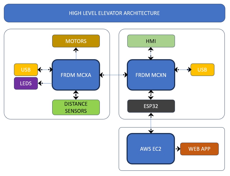
Initially I wanted a distributed system where each Microcontroller has a specific function. FRDM-MCXN236 with its higher processing power will be main controller which will be used to control the MCXA153 board which will control the motor, LED indication, monitor the distance at which the lift is in, and report to MCXN236. MCXN236 will share the telemetry using ESP32 which facilitates the network option.
Since the MCXN236 is also peripheral rich and comes with CAN supports, flexible number of UART, I wanted to make use of at least one peripheral of each type.
UART – Communication between MCXN236 and HMI display

SPI – Communication between MCXN236 and MCXA153

CAN - Communication between MCXN236 and ESP32

I2C - Communication between MCXA153 and ToF sensor
When I made these decisions, I didn’t factor in complexity of enabling and using these peripherals for the purpose they are made.
Web App
The idea is to gather the telemetry data from the lifts and analyze, present it in a dashboard. The data can further be used to optimize the logic the lift operates so that if any particular lifts is repeatedly used more than other, it can be avoided.
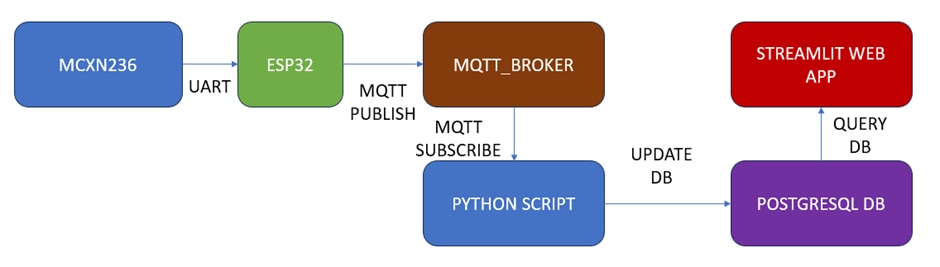
An ESP32 Dev Kit board will be used to get the lift events from MCXN236 board. The data will be in a binary code format with each byte denotes the floor number, whether its travelling to a particular floor, whether there are any faults. The data will be transmitted to a MQTT broker. A python script will continuously monitor the particular topic and once the message is received, it will parse the binary data to its proper definitions. Then it will push the data entry to postgresql db.
The web app is actually a python software created using Streamlit library. Streamlit library provides a faster way to visualize data by integrating various libraries like matplotlib, plotly. The Streamlit application will frequently query the database and update the dashboard. Below are the videos of simulated data to check whether the web app is working.
The below is a video of transmitting simulated lift data using MQTT
Below is the video of a python script that subscribes and receive the mqtt messages and push into database.
Below is a video recording of streamlit app that fetches the data from Postgresql db and create charts based on it.
I tried uploading the python scripts, but this site blocked me from doing it.
Planning and Preparation
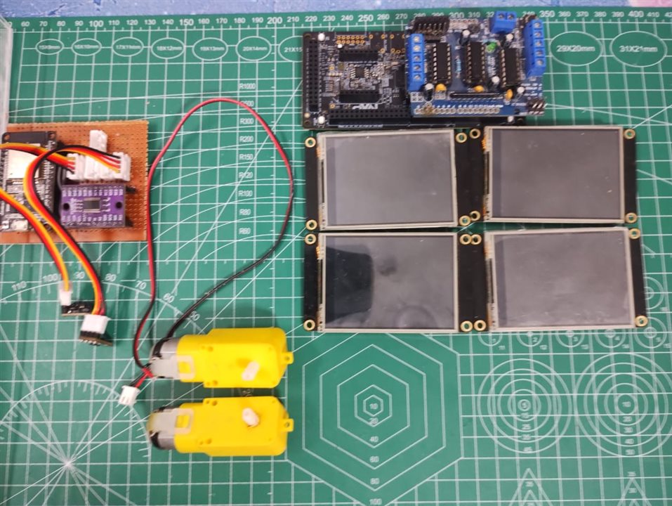
I have written few forum posts discussing how I selected the HMIs, and ToF sensors, and what purpose they serve.
DDS Elevator - Bit of human touch - element14 Community
DDS Elevator - Measuring up - element14 Community
To be honest I am actually happy when resolving issues that required multiple UART to control HMI or multiple I2C port to read distance reading from 3 ToF sensors. Especially using a single UART to control multiple HMIs. The concept of daisy chaining was new to me, and I found out only when I was researching on a suitable application for Experimenting with Single Pair Ethernet
Basic Elevator logic
In the first forum post I have described the logic in which elevators are assigned.
Case 1:
None of the elevators are operating, then select the first elevator nearby
            for (int i = 0; i < MAX_FLOOR; i++)
            {
                if (!lifts[i].busy)
                {
                    bestLift = i;
                    break;
                }
            }
case 2:
If there is already an elevator travelling towards to that destination, assign it to user
        if (lifts[i].busy)
        {
            for (int j = lifts[i].serviceRequest; j < lifts[i].totalRequests; j++)
            {
                if (lifts[i].targetFloor[j] == destinationFloor)
                {
                    bestLift = i;
                    break;
                }
            }
        }
case 3:
If none of the travelling elevators are reaching that destination, assign one that travels in the same direction user wants to travel to.
        for (int i = 0; i < MAX_FLOOR; i++)
        {
            if (lifts[i].busy && lifts[i].direction == travelDirection)
            {
                if (travelDirection == 1 && lifts[i].currentFloor < requestFloor)
                {
                    bestLift = i;
                }
                if (travelDirection == -1 && lifts[i].currentFloor > requestFloor)
                {
                    bestLift = i;
                }
            }
            if (bestLift != -1)
            {
                break;
            }
        }
I wanted to test these algorithms using the boards but unfortunately, I could not reach that point, so reliability of these codes can't be stated. I have attached my MCXN236 project files with this lift logic.
Challenges and Roadblocks
Once the components are selected, I started exploring the SDKs and programmed the devices without using example code. It is at that point troubles started happening. Most of the examples uses a default peripheral instance and those worked without any glitch. Enabling another instance of same peripheral family started introducing new issues which took some time to resolve.
When working in non-blocking mode, we could receive only 4 bytes of data during interrupt operation which is not enough for receiving data from HMI (13bytes)
For example, the automatic code generation for LPUART assumed all UART will use the same code which was not the issue for certain pins which are configured as UART.
DDS Elevator - Enabling LPUART in N236 board for Serial communication - element14 Community
Sometimes, the IDE will stop working when flashing the firmware and requires a separate flashing tool. This stops us from using simple debugging procedures.
Besides these, introducing multiple controllers increased the complexity of the project. It is at this point few weeks ago, I decided initial architecture plan won’t work at all.
Updated version

My first significant change was moving the measurement of distance using MCXA153 board to ESP32. Considering LEDs causes fluctuations in ToF sensor, LED indication will be removed and all the key information will be depicted in HMI. Since motor control is a simple process, MCXN236 board alone can take care of it there by eliminating the need for MCXA153.
CAN communication proved challenging as well; to avoid spending more time on it, I replaced the communication protocol between MCXN236 and ESP32 to UART.
Show stopper
To be honest, I should have decided to move the I2C sensor to ESP32 once I spend multiple weeks trying to make it work with either MCXA153 or MCXN236 boards. Even with the deadline extended, configuring the peripherals took too much time which could have been spend on the logic and making the working model.
After all these trials and errors, making each peripherals work and going through the trouble of coming up ways to interface multiple displays/sensors, I don’t have any demo to show for it. I feel embarrassed for participating in this challenge and making it look like one of the road test entries.
Lessons learned
I made a mistake of attempting a large-scale project when I have no experience with the Microcontroller provided to do it. I didn’t expect the controllers itself will be a bottleneck. Attempting something entirely new without some familiar controller ecosystem hit in the back.
Looking back, I realize I have left out several points when writing the posts in a hurry. I should make it a habit of noting down important points in a workspace somewhere so that I could add them later in the forum posts.
After relying on AI for spell checking, restructuring, I realized it lacks the human touch and stopped using AI for such purpose from second post onwards.
Feedback on boards
I think I still standby my experience on these boards as I stated earlier. There are lots of bugs in the SDKs and IDEs itself which make impacts the user experience. I don't think these will be my go-to boards for future projects. Compared to the limited user base MCX series has considering it is a newly launched MCU family, it might take some time for the SDKs to be stable for fast development purpose.
Conclusion
This is my first design challenge, and I am kind of sad that I could not complete what I wanted to make. Still, I am glad about all the experiments I have done with these microcontrollers, and I can honestly say I gave it my best effort. It was fun engaging with other contestants and solving each other’s issues.
A huge thanks to Element14 and NXP for sponsoring this contest!
Top Comments