


Table of Contents
Introduction
Since configuring UART is slightly complex and there is no proper tutorial on how to configure multiple UART to use and receive in a non-blocking manner, I have decided to write this blog to help others who might be in need of this. For this example, we will enable the default UART and the UART pins connected in the Micro Bus extension.
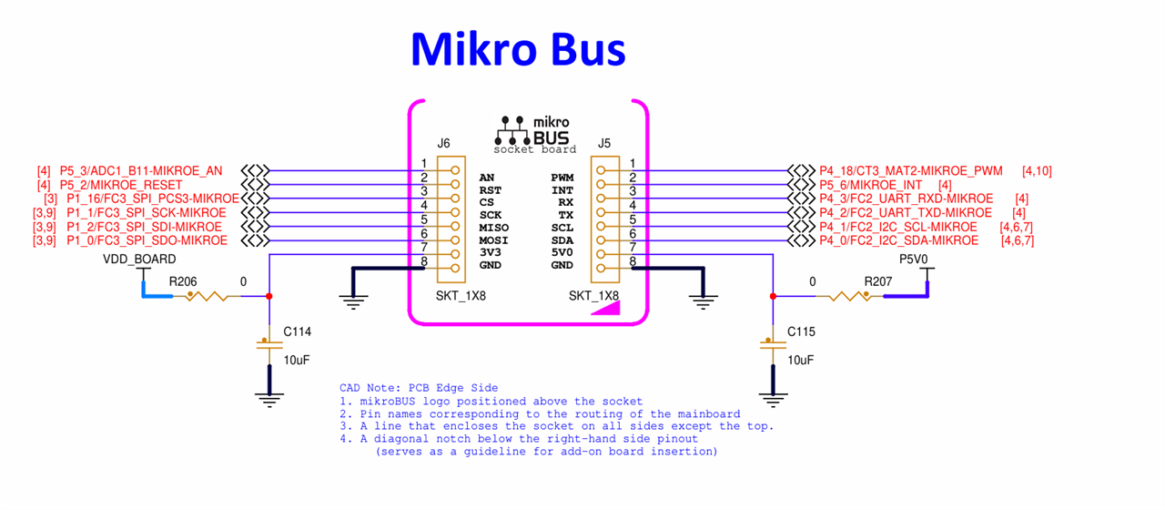
Pin Configuration
| Peripheral | Rx Pins | Tx Pins |
|---|---|---|
| Default | P1_8 | P1_9 |
| MicroBus | P4_2 | P4_3 |


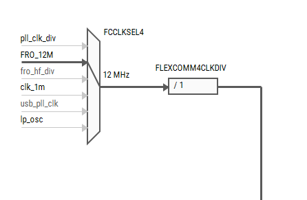
Clock
We will use 12Mhz clock for both FC2 and FC4. From the clock page, activate clocks for both FlexComm peripherals.


Peripheral
We are not going to use DMA or RTOS, we will use the basic Device specific driver for this.

Transfer Method
Instead of polling method, we will use transfer method which is versatile and can be used either in blocking mode or as non-blocking mode.

We can capture more bytes at a same time, but it’s hard to know the amount of received data. Let’s say for example, we want to receive 10 bytes as default, and we receive only 5 bytes, the rx buffer will receive the minimum of both size which is 5 bytes, but we won’t know this detail when call back is triggered. So, for this example, we will receive one byte at a time.

Callback
Unless we configure the callback, we will have to rely on the return statement of
LPUART_TransferReceiveNonBlockingfunction which is not reliable in knowing how many bytes we have in our buffer. Lets enable the callback and give the name as "cb_rx".

These are the configurations we need to get UART receive in non-blocking mode. Now select "Generate Code". Once the code is generated, try to build the application. It will throw error as we have not defined what our callback function does.

void cb_rx(LPUART_Type *base, lpuart_handle_t *handle, status_t status, void *userData)
{
	if(status == kStatus_LPUART_RxIdle && base == LP_FLEXCOMM4_PERIPHERAL)
	{
		LPUART_WriteBlocking(LP_FLEXCOMM4_PERIPHERAL, LP_FLEXCOMM2_rxBuffer,1);
	}
}
Add this code in main c file. Now the build will succeed. What we are trying to do is, on receiving the callback, we will print the first character stored in our receive buffer using default UART.
Modifying Driver code
Since we are using I2C pins which can be configured as Rx/Tx pins of FC2, we need to ensure the UART is properly initialized. Unfortunately, the driver code automatically doesn't take care of this, and we need to make some manual changes in the fsl_lpuart.c in the LPUART_Init function.
    	if(base==(LPUART_Type *) LP_FLEXCOMM2_BASE)
    	{
    		status = LP_FLEXCOMM_Init(LPUART_GetInstance(base), LP_FLEXCOMM_PERIPH_LPI2CAndLPUART);
    	}
    	else
    	{
    		status = LP_FLEXCOMM_Init(LPUART_GetInstance(base), LP_FLEXCOMM_PERIPH_LPUART);
    	}
Configuring Read Non-blocking function
For this example, we will connect the Tx of FC2 to Rx of FC2 so we will verify the working by using this loopback setup. We will transmit test data every 1s and check whether we are receiving the same.
To get the callback the read non-blocking repeatedly.

void testData()
{
	static uint32_t prevCounter = 0;

	if( ms - prevCounter > 1000 )
	{
		prevCounter = ms;
		LPUART_WriteBlocking(LP_FLEXCOMM4_PERIPHERAL,(uint8_t *)"TestData\n", 9);
	}
}

    while(1)
    {
    	testData();
    	(void)LPUART_TransferReceiveNonBlocking(
    			LP_FLEXCOMM2_PERIPHERAL, 	// MicroE extension uart
				&LP_FLEXCOMM2_handle,		// FC2 Transfer Handle
				&LP_FLEXCOMM2_rxTransfer,	// FC2 Receive buffer details;
				&receivedBytes				// dummy variable. No idea what it actually does
				);
    }
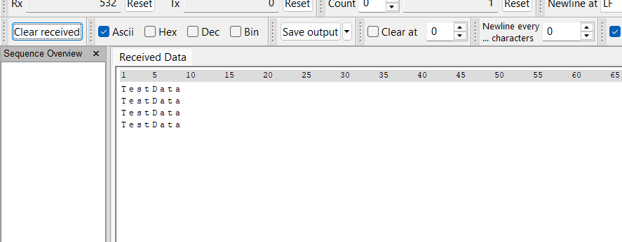
Output
Now, build and flash the firmware in the N236 board. Open the serial terminal and we will see "TestData" printed every one second.
Conclusion
Although this is not in my intended list of forum post, I want to keep this process documented so that it will be useful for anyone who is facing the same issue.


