

Table of contents

Abstract
This project is a prototype for a smart exhaust fan that adjusts its speed based on the building's air quality. This is suitable for applications such as 3D printer farms and crowded rooms, where air quality can fluctuate.
Project
Description
This project demonstrates a smart exhaust fan prototyped using the FRDM-MCXN236 development board. It demonstrates the prototype of a low-power exhaust fan that controlled by the MCXN236 MCU based on air quality and commands received via Wi-Fi.
The main application for this prototype is
- 3D Printing Farms where operations can result in release of volatile organic compounds (VOCs)
- Bars/Meeting Rooms to eliminate odors
- Protecting vulnerable population from allergies etc.
The project consists of the following components:
- FRDM-MCXN236 MCU - The MCX N series MCU at the heart of the application
- EMC2101 Fan Controller (Link)
- BME688 breakout (Link)
- WizFi 360 board (Link)
- 5V DC Motor Fan (Link)
System Overview
This section documents the details of the low power and smart exhaust fan operation.
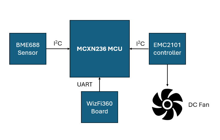
- The BME688 sensor measures the volatile organic compound levels (VOCs) and sensitive to a range of VOC compounds. It interfaces with the MCU via the I2C interface (LPI2C2) and its device address is 0x77.
- The EMC2101 controller is responsible for controlling and operating a DC fan. It interfaces with the MCU via the I2C interface (LPI2C2) and its device address is 0x4C.
- The WizFi360 shield is used to send data and receive commands from the cloud. The shield interfaces via the UART interface.
- The FRDM-MCXN236 is at the heart of this project. It makes use of the BME688 sensor data and runs a TinyML algorithm to detect odors. Based on the odors detected and/or air quality levels, the MCXN236 operates the DC fan using the EMC2101 controller. It makes use of the WizFi360 to upload data and receive commands via the UART interface.
The project below identifies the components in a photograph.

Here is a video of the project in action:
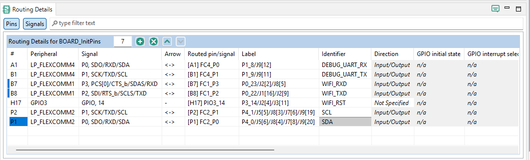
Pinout
The figure below shows a list of pins used in this project:
Board Bring-Up
The upcoming sections documents the bring-up of each component and the challenges encountered. It also documents the work left with the bring-up of the component.
WizFi360 Shield
The WizFi360 shield is interfaced to MCXN236 using LPUART1 (via LPFLEXCOMM1). It makes use of the Arduino shield pins D7 and D8. The shield is used to upload data and receive commands from the cloud. The challenge encountered while interfacing the shield was getting the UART interface working to send AT command. With the help of the logic analyzer, it was determined, there was no output on the UART interface. As mentioned in this post, the UART interface LPUART1 worked only when it was configured as follows:
status = LP_FLEXCOMM_Init(LPUART_GetInstance(base), LP_FLEXCOMM_PERIPH_LPI2CAndLPUART);
instead of
status = LP_FLEXCOMM_Init(LPUART_GetInstance(base), LP_FLEXCOMM_PERIPH_LPUART);
To avoid breaking the auto-generated code, the UART initialization sequence in lpuart.c was modified as shown below.
#if !(defined(LPFLEXCOMM_INIT_NOT_USED_IN_DRIVER) && LPFLEXCOMM_INIT_NOT_USED_IN_DRIVER)
/* initialize flexcomm to LPUART mode */
if(base==(LPUART_Type *) LP_FLEXCOMM1_BASE)
{
status = LP_FLEXCOMM_Init(LPUART_GetInstance(base), LP_FLEXCOMM_PERIPH_LPI2CAndLPUART);
}
else
{
status = LP_FLEXCOMM_Init(LPUART_GetInstance(base), LP_FLEXCOMM_PERIPH_LPUART);
}
if (kStatus_Success != status)
{
return status;
}
#endif /* LPFLEXCOMM_INIT_NOT_USED_IN_DRIVER */
It is not clear why this modification was necessary. After the modification, the UART interface was operational. The logic analyzer output below shows the AT commands and their response via UART. The AT commands driver was ported from here.
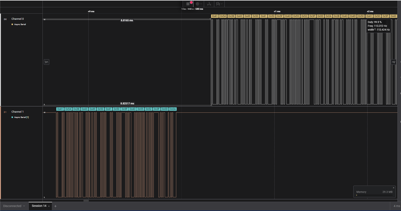
The WiFi driver is operational but the ability to upload data and receive commands is a work in progress.
BME688 Sensor
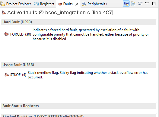
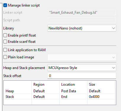
The BME688 breakout board is interfaced to the MCXN236 via LPI2C2 (configured via LPFLEXCOMM2). The drivers for the BME688 were available from here and here.The biggest challenge with interfacing this sensor was the stack requirements. Initially, this project was kicked off with the FRDM-MCXA153 board. But there wasn't enough memory and resulted in a stack overflow (as documented in this post).
Even after making multiple attempts, it was very difficult to get the sensor interfaced to FRDM-MCXA153.
After switching to FRDM-MCXN236, the stack size had to be increased to 16kB. It was smooth sailing after bumping up the stack size and the FRDM-MCXN236 was a perfect fit for the sensor.
The video below shows the live sensor output from the BME688 via the debug UART console.
The BME688 provides an estimate of the VOC compounds using a Bosch licensed algorithm. This algorithm is available through a static library downloaded from Bosch's website.
TinyML algorithm
This section is a work in progress. The intent is to use BME688 AI studio and to build a C library to detect odors. In order to accomplish this, data collection and training are required. This is currently in progress.
EMC2101 driver
The EMC2101 driver was ported from here. The breakout board is interfaced via LPI2C2. The DC fan controller is used to regulate the speed of the fan based on the air quality data. This enables turning off the fan when the air quality is normal and turning it on only when required. The EMC2101 controller is vital to making this a low power application.
The video below shows the EMC2101 reading the RPM and the external temperature. There are some issues with printing float variables to the debug console that need to be resolved in the project's properties.
Next Steps
The proof of concept for this project is now complete. The following are the next steps:
- Uploading data and receiving commands via an MQTT server. The WizFI360 driver needs to be modified slightly to accomplish this.
- TinyML algorithm training and build to enable odor detection
- Debug printf modification to accommodate float variables
- Integrating EMC2101 to vary fan speed according to TinyML algorithm data.
- FreeRTOS adoption to handle all tasks using a scheduler. A state machine would be appropriate as well.
- Adoption of the second core available on the MCXN236.
- Custom printed circuit board (PCB) design to bring all components into one board.
Github Repository
The code for this project is available from here.
Conclusion
This project has been a solid learning experience. The intent is to take this project forward and build a product around it. The author expresses gratitude for the opportunity to road test the MCX series microcontrollers.
Top Comments