


1.General Introduction
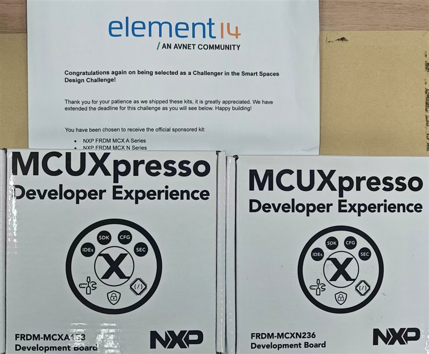
Smart Spaces Design Challenge to develop innovative solutions using NXP’s FRDM MCX A Series (A15X) development kit to create a smart space, smart warehouse or tackle a building automation problem. There are two boards provided,
NXP FRDM A - MCX Freedom Development Board, MCXA153, 32bit, ARM Cortex-M33, Quick Start Guide, USB Type-C Cable,
&
NXP FRDM MCX N - Development Kit, MCXN236VDFT, MCXN23x, 32bit, ARM Cortex-M33
2. FRDM-MCXA153 Development Board Unboxing
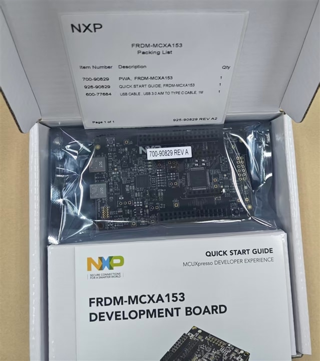
2.1 Typical Kit Contents
As a standard NXP FRDM series evaluation board, the FRDM-MCXA153 kit includes the following items, packed in a protective cardboard box to prevent damage during transportation:
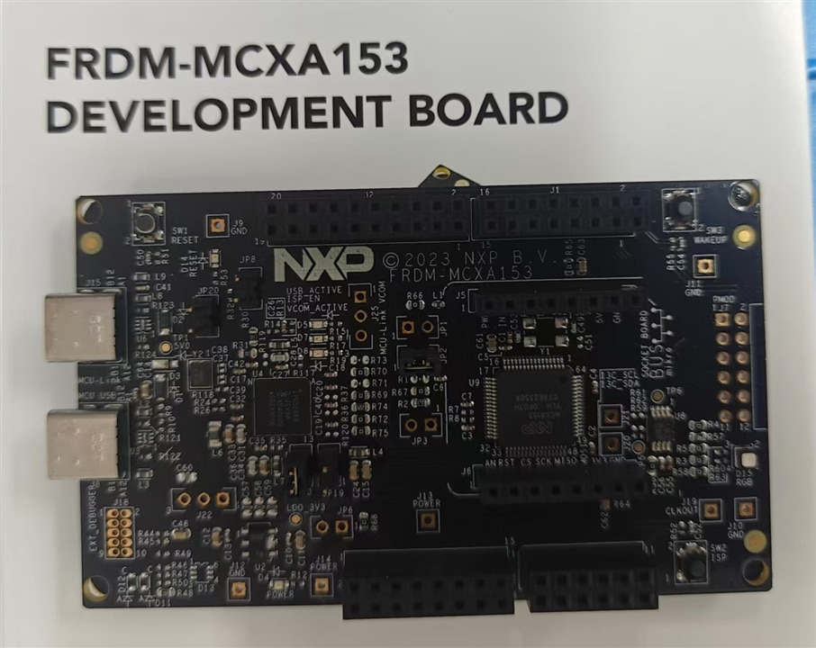
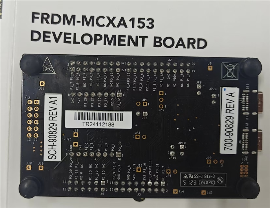
- 1 x FRDM-MCXA153 Main Board: The core component, built around the NXP MCX A153 microcontroller (MCU). The board features a compact printed circuit board (PCB) design with clearly silkscreened labels for connectors, buttons, and LEDs, making it easy for users to identify and operate.
- 1 x USB 2.0 Type-A to Type-C Cable (1 Meter): A durable, standard-length cable used for two key purposes: powering the board and establishing USB communication (such as debugging via the onboard MCU-Link probe or data transmission through the USB full-speed interface).
- 1 x Quick Start Guide: A user-friendly document that provides step-by-step instructions for initial setup, including how to power the board, install necessary drivers , and access basic example projects. It also includes links to NXP’s official resources, such as the MCUXpresso IDE download page and the board’s technical reference manual.
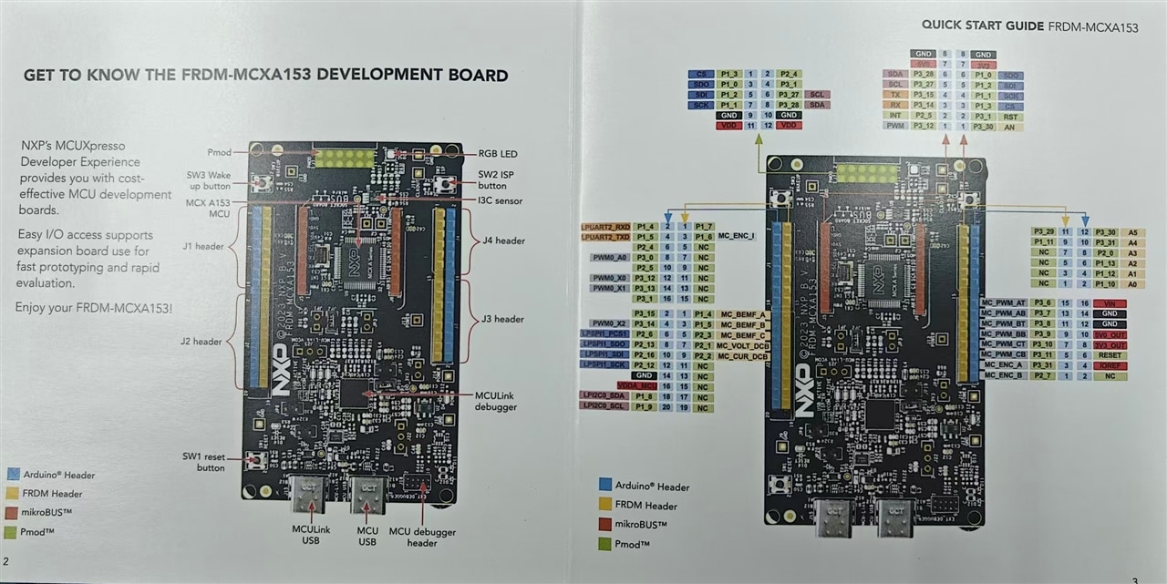
2.2 Key Hardware Highlights (First Look)
When you take the FRDM-MCXA153 board out of the box, the following hardware components are the most prominent and worth noting:
- Target MCU (MCX A153VLH): The "brain" of the board, based on an Arm Cortex-M33 core with a maximum operating frequency of 96 MHz. It is optimized for low-power industrial and consumer IoT applications, supporting features like industrial communication protocols, brushless direct current (BLDC) / permanent magnet synchronous motor (PMSM) control, and integrated sensor interfaces (MIPI I3C, I2C, SPI).
- Onboard Debug Probe (MCU-Link OB): Integrated on the board, this probe is based on the NXP LPC55S69 MCU. It enables seamless serial wire debug (SWD) for the MCX A153 MCU and provides a USB-to-UART virtual communication (VCOM) port for data transfer. It connects to a PC via a dedicated USB Type-C connector
- Expansion Connectors: To support flexible project expansion, the board is equipped with multiple industry-standard connectors:
- 4 Arduino UNO R3-compatible sockets for compatibility with a wide range of Arduino shields
- 2 mikroBUS sockets (labeled J5-J6) for Mikroe "click boards"—plug-and-play modules that add specific functions like GPS, Wi-Fi, or environmental sensing.
- 1 Pmod connector for Digilent Pmod peripherals, expanding options for custom I/O and communication.
- User Interface Components: For basic human-machine interaction and status monitoring:
- 3 push buttons: SW1 (Reset, to restart the target MCU), SW2 (ISP mode, to force the MCU into In-System Programming mode for firmware updates), and SW3 (Wake-up).
- Multiple LEDs: A green power LED (indicating the board is powered on), a red reset LED (lighting up during reset operations), a user-controllable RGB LED (for custom status indication via software), and 3 MCU-Link-specific LEDs (showing USB connection status, ISP mode, and VCOM data activity).
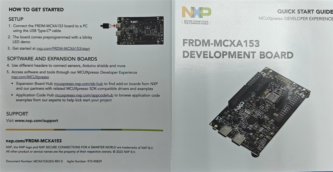
2.3 Initial Setup Tips
- Board Inspection: Before powering on, visually check the board for any physical damage, such as bent pins on connectors or loose components.
- First Power-Up: Use the included USB cable to connect the MCU-Link USB connector to a PC. The green power LED should illuminate immediately, indicating the board is receiving 5V power
- Debugger Recognition: The onboard MCU-Link probe comes preprogrammed with NXP’s CMSIS-DAP firmware. Most modern operating systems will automatically detect the probe and install generic drivers.
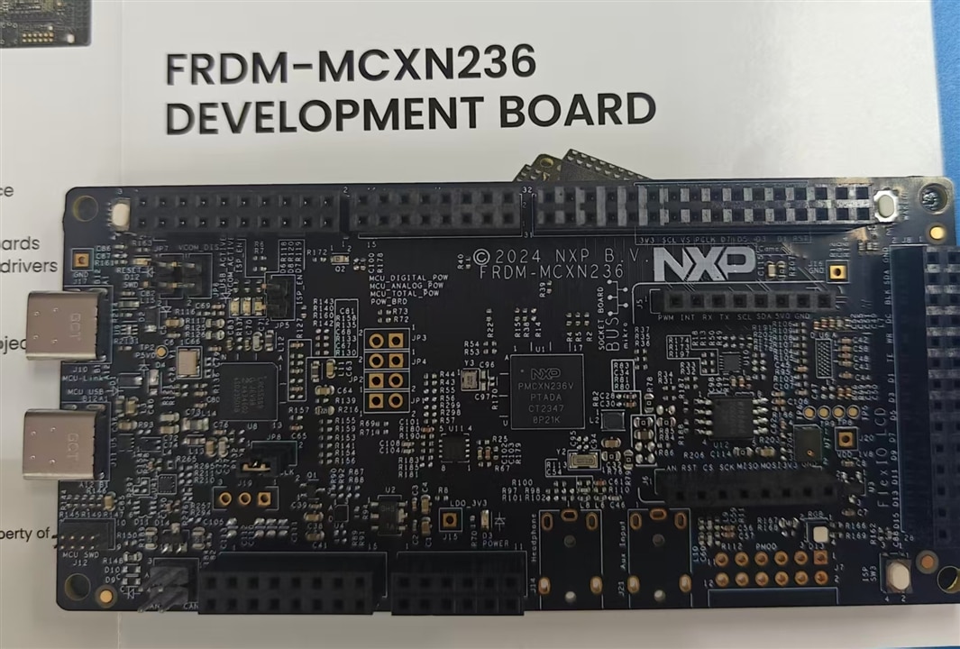
3. FRDM-MCXN236 Development Board Unboxing
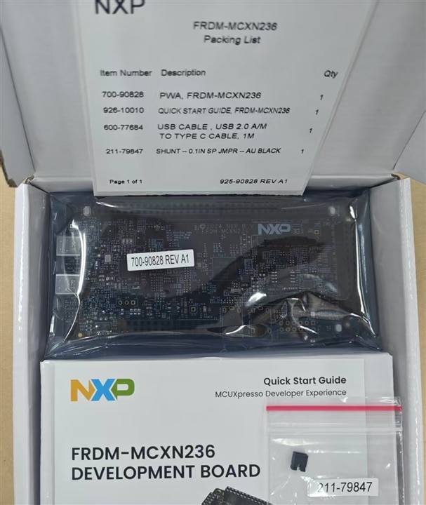
3.1 Typical Kit Contents
Similar to the FRDM-MCXA153, the FRDM-MCXN236—another member of NXP’s FRDM series—typically includes the following items in its kit, designed for ease of use and immediate setup:
- 1 x FRDM-MCXN236 Main Board: Larger in size than the FRDM-MCXA153 (common dimensions for FRDM-MCXN236 are around 118 mm x 55 mm), it is built around the NXP MCXN236 MCU. The PCB is more densely populated with integrated peripherals, catering to more complex IoT and industrial application prototyping.
- 1 x Micro USB Type-A to USB Type-C Cable (3 Feet / ~0.9 Meters): A shorter, portable cable compared to the one included with the FRDM-MCXA153. It is used to power the board and connect to the MCU-Link probe or the board’s high-speed USB interface.
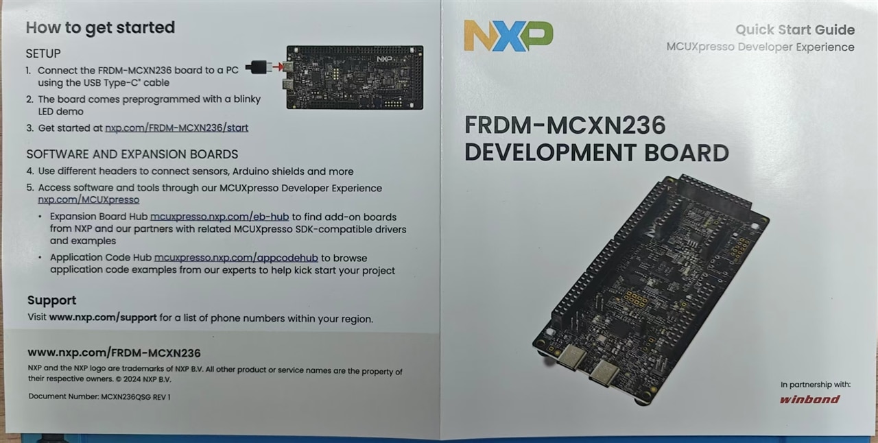
- 1 x Quick Start Guide: Similar to the FRDM-MCXA153’s guide, it offers simplified setup instructions, driver installation tips, and links to resources like the MCXN236 MCU’s data sheet and NXP’s software development tools.
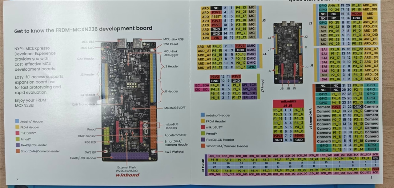
3.2 Key Hardware Highlights (First Look)
The FRDM-MCXN236 stands out for its richer integrated peripherals, making it suitable for prototyping projects requiring advanced features. Here are the key components to notice:
- Target MCU (MCXN236): An Arm Cortex-M33 MCU with TrustZone security features, designed for secure IoT applications. It supports high-speed USB 2.0 (both Device and Host modes), flexible controller area network (FlexCAN) for industrial communication, and advanced I/O capabilities for multimedia and sensor integration.
- Integrated Peripherals :
- 64 Mbit QSPI Flash (Winbond W25Q64JVSSIQ): Soldered directly on the board, providing ample storage for firmware, application data, and configuration files.
- FXLS8974CFR3 3-Axis Accelerometer: A low-power motion sensor that enables projects like activity detection or tilt sensing, connected via the MCU’s I2C interface.
- Visible Light Sensor: Used to evaluate the MCU’s analog-to-digital converter (ADC) module, allowing users to measure ambient light intensity.
- TJA1057GTK/3Z CAN PHY: A high-speed CAN transceiver with CAN FD (Flexible Data Rate) support, paired with a 4-pin CAN header (for connecting to external CAN bus networks), ideal for industrial automation projects.
- Digital Microphone : For audio input prototyping, supporting pulse-density modulation (PDM) output, and a placeholder for an audio codec (DA7212, not populated by default) for expanded audio functionality.
- Expansion Connectors:
- 4 Arduino UNO R3-compatible headers (J1-J4) for compatibility with Arduino shields .
- 2 mikroBUS headers (J5-J6) for Mikroe click boards, adding functions like wireless communication (Wi-Fi, Bluetooth) or environmental sensing (temperature, humidity).
- 1 FlexIO Header (J8): A 28-pin connector designed for LCD displays (e.g., NXP’s PAR-LCD-S035 low-cost LCD module) and other high-speed I/O applications.
- 1 Camera Header (J9): A 32-pin connector tested with cameras like the OV7670, enabling image capture and processing projects.
- User Interface Components:
- 3 push buttons: SW1 (Reset), SW2 (Wake-up), SW3 (ISP mode).
- 4 LEDs: D3 (green, power status), D12 (red, reset status), D13 (RGB, user-controllable via software), and 3 MCU-Link LEDs (D6 for USB activity, D7 for ISP mode, D8 for VCOM data transmission).
3.3 Initial Setup Tips
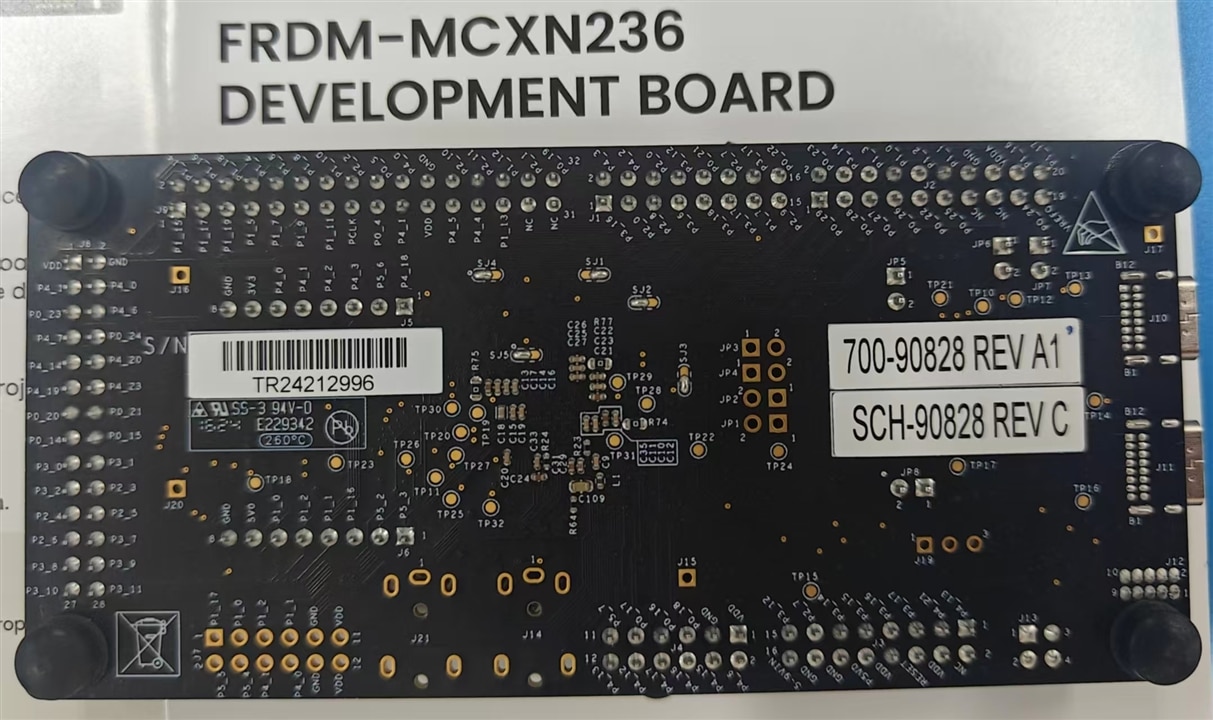
- Board Inspection: Due to the dense peripheral population, check the FRDM-MCXN236 board carefully for any loose components or bent pins . The bottom of the board may have additional test points for measuring power consumption or signal integrity.
- First Power-Up: Connect the included USB cable to the MCU-Link USB connector on the board and a PC. The green power LED (D3) will turn on when the board receives stable power.
- Debug and USB Preparation: The MCU-Link probe on the FRDM-MCXN236 supports both CMSIS-DAP and J-Link firmware (preloaded with CMSIS-DAP).
4. Next
The size is different
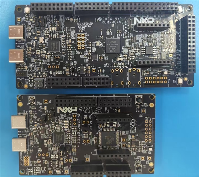
In all, FRDM-MCXN236 is especially better in performance for AI application such as voice, video process.
Next , install the software and try demos.
