


In every elevator, there is an option for the user to select which floor they want to travel to. In case of DDS elevators, there will be feedback which immediately shows which elevator was assigned to them. In this blog, we will see how to interface human interaction between our lift model to our microcontroller through the use of HMIs. We will also cover the struggles it took to get the concept working.
Table of Contents
Why HMI
HMI provides a way for humans to provide their input and receive feedback immediately. While I could simplify the process using buttons for inputs and LEDs for feedback, it will include using lots of GPIOs and way too many wirings.
Imagine for a single floor, we need 4 buttons to get user input on floors, 1 RGB led with different light configuration for different statuses. That makes each floor requiring 5 GPIOs. Now, for our lift model, we have 4 floors and that makes 16 buttons to get user input and 4 RGB LEDs. We could reduce the number of GPIOs required by 4*4 matrix keyboard and bit addressable RGB LEDs. That still requires up to 9 GPIOs.
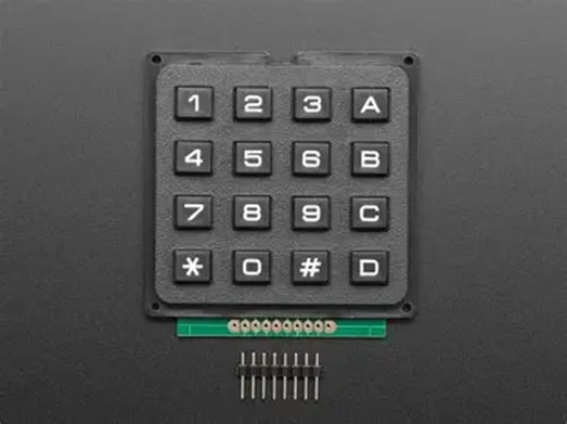
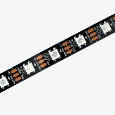
Now, HMIs on the other hand, depending on the model can be operated by using just UART alone. That’s just 2 GPIOs for one floor, 8 GPIOs for 4 floors. Since it is a touch supported HMI, we could get user input and provide feedback on display.
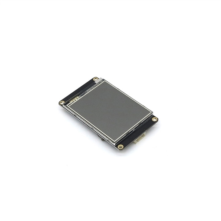
For this project we will use a 2.8” touch display from Nextion Brand. It is a resistive touch display and cheaper.
Struggling with setting up multiple UART
Initially I wanted to use FRDM MCXA153 to control the HMI but when I tried to enable the second UART, it stopped working. So, I moved to MCXN236 board. Even there I faced similar issues. There is a UART port exposed as a Micro Bus expansion, which didn’t work as well. Luckily MCXN236 has multiple UART ports and one of them is exposed in the LCD header. On configuring that particular port, second UART was up and running.
Scalability issue
Since we have finalized to use 4 HMIs, we need to look for ways to minimize the number of wires. Each HMI comes with 4 pins – Vcc, Gnd, Rx, Tx. Supply and ground wires can be taken parallelly from a power source. But we still need to route 8 wires for UART.
Initial idea
My initial horrible plan was to make use of multiple MCUs each reporting back to MCXN236 board. MCXA153 has one extra UART port, ESP32 has 2 extra UART ports, and with one already working UART from MCXN236 combining all these resources we could wire something like this.,
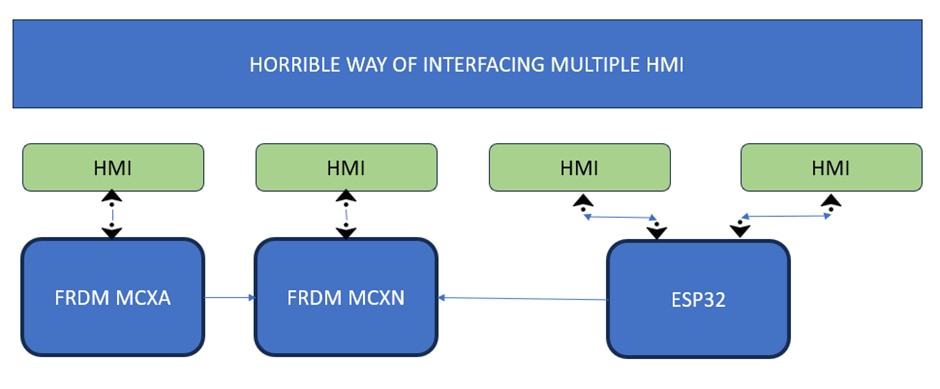
Just looking at the above block diagram made it obvious this is a ridiculous way of connecting multiple HMIs, so I dropped this idea and decided to try an alternative.
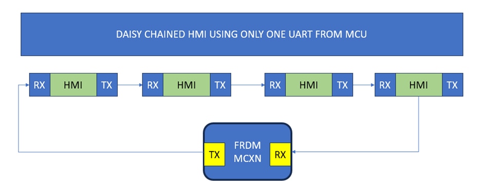
Daisy chaining
Daisy chaining is a simple interface method where we connect multiple nodes in a linked list manner. I got this idea from Ethercat communication which uses two ethernet port, one will act as input and other as output.
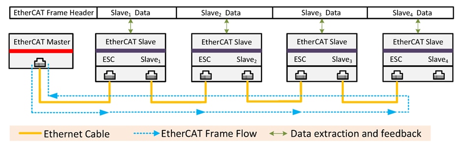
The Ethercat master will send a process image, with request to fill the process image with data from slaves or update the slaves from the process image. By slightly modifying this for UART, we can use Tx as output port and Rx as input port.
Programming the HMIs
Nextion provides an application called “Nextion Editor” which can be used to design the UI. It also provides simulation mode to immediately visualize the changes.
Since steps to cover how to program an HMI display out of topic for this post, I will add few links in reference.
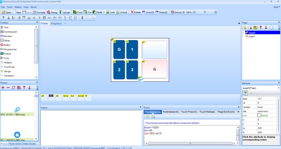
UI – Dynamic Floor selection
Instead of programming each HMI display with a different identification number, I have decided to create a configuration page where the floor in which display will be placed can be selected.
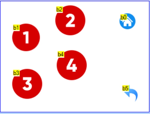
Values start with 0 for button 1, 1 for button 2 and so on. For example, on pressing the number 4, the value “3” will be written to memory ().
wepo 3,10
wepo is the write to EEPROM memory command, 3 is the identification for 4th floor and 10 is the address we are writing to.
On pressing the home icon, the HMI will restart. On initializing, it will read from memory address 10 and store the floor value in a variable for further use.
repo liftID.val,10
repo is the read from EEPROM memory command to read from the memory address 10 and store into variable called “liftID”.
UI – Getting user input
The HMI has few a variable initialized to “0xff” value. When user press a button, HMI will update the internal value like this. There is a timer which monitors the variable, once it detects the value is not “0xff”, it transmits the current value to next node and reset back to “0xff”.
Button value = Floor ID * 10 + Selected Floor num.
Example, if a user press button labelled 2 on 2nd floor, it will be saved as 32. The HMI will transmit the value as “but.val=32” which will update the variable of next node, and the process will continue until the message reaches the MCU.
Below is the screen record of the HMI logic in a simulator.
UI – Feedback response from microcontroller
There are two types of feedback.
- Whether the elevator will go up, down, or rejected on pressing the button.
- Which elevator to select.
The message format is similar to getting input from user. There will be a commonly named variable which will be updated and passed on until it reaches the correct end node.
I have created a simple code to check whether the logic works when used with MCXN236. Below are the videos I took when I tried to control only one HMI and with two HMIs. I am glad to find after all these ordeals, I got it working.
Conclusion
To be honest, neither the HMI UI design nor daisy chaining multiple UART is not the difficult part. I have worked with various HMIs, and I could set it up with MCUs from ST or Espressif without much difficulty. What I didn’t expect was how difficult it will be to enable a second UART in MCXN board and make it usable. This is slightly disappointing as I want to use one instance of most of the communication peripheral in that board. Anyways, we will see how to establish communication between MCXA and MCXN board in the upcoming post.