element14 Community
element14 Community
    Register Log In
  • Site
  • Search
  • Log In Register
  • Community Hub
    Community Hub
    • What's New on element14
    • Feedback and Support
    • Benefits of Membership
    • Personal Blogs
    • Members Area
    • Achievement Levels
  • Learn
    Learn
    • Ask an Expert
    • eBooks
    • element14 presents
    • Learning Center
    • Tech Spotlight
    • STEM Academy
    • Webinars, Training and Events
    • Learning Groups
  • Technologies
    Technologies
    • 3D Printing
    • FPGA
    • Industrial Automation
    • Internet of Things
    • Power & Energy
    • Sensors
    • Technology Groups
  • Challenges & Projects
    Challenges & Projects
    • Design Challenges
    • element14 presents Projects
    • Project14
    • Arduino Projects
    • Raspberry Pi Projects
    • Project Groups
  • Products
    Products
    • Arduino
    • Avnet & Tria Boards Community
    • Dev Tools
    • Manufacturers
    • Multicomp Pro
    • Product Groups
    • Raspberry Pi
    • RoadTests & Reviews
  • About Us
  • Store
    Store
    • Visit Your Store
    • Choose another store...
      • Europe
      •  Austria (German)
      •  Belgium (Dutch, French)
      •  Bulgaria (Bulgarian)
      •  Czech Republic (Czech)
      •  Denmark (Danish)
      •  Estonia (Estonian)
      •  Finland (Finnish)
      •  France (French)
      •  Germany (German)
      •  Hungary (Hungarian)
      •  Ireland
      •  Israel
      •  Italy (Italian)
      •  Latvia (Latvian)
      •  
      •  Lithuania (Lithuanian)
      •  Netherlands (Dutch)
      •  Norway (Norwegian)
      •  Poland (Polish)
      •  Portugal (Portuguese)
      •  Romania (Romanian)
      •  Russia (Russian)
      •  Slovakia (Slovak)
      •  Slovenia (Slovenian)
      •  Spain (Spanish)
      •  Sweden (Swedish)
      •  Switzerland(German, French)
      •  Turkey (Turkish)
      •  United Kingdom
      • Asia Pacific
      •  Australia
      •  China
      •  Hong Kong
      •  India
      •  Korea (Korean)
      •  Malaysia
      •  New Zealand
      •  Philippines
      •  Singapore
      •  Taiwan
      •  Thailand (Thai)
      • Americas
      •  Brazil (Portuguese)
      •  Canada
      •  Mexico (Spanish)
      •  United States
      Can't find the country/region you're looking for? Visit our export site or find a local distributor.
  • Translate
  • Profile
  • Settings
Smarter Life
  • Challenges & Projects
  • Design Challenges
  • Smarter Life
  • More
  • Cancel
Smarter Life
Blog Post 10: Smarter Life Challenge: Oven Control with PSOC 4
  • Blog
  • Forum
  • Documents
  • Files
  • Events
  • Mentions
  • Sub-Groups
  • Tags
  • More
  • Cancel
  • New
  • Share
  • More
  • Cancel
Group Actions
  • Group RSS
  • More
  • Cancel
Engagement
  • Author Author: malamitra
  • Date Created: 10 Jan 2014 2:21 PM Date Created
  • Views 744 views
  • Likes 2 likes
  • Comments 1 comment
  • psoc4
  • smarter_life_challenge
  • oven_control
  • smarter_life
Related
Recommended

Post 10: Smarter Life Challenge: Oven Control with PSOC 4

malamitra
malamitra
10 Jan 2014

Topic: PID in hardware


Keywords: Op-amp, differentiators, integrators, simulation, TINA-TI


For implementation of PID dual-supply op-amps are required. A positive supply op-amp can be used with the input given at the non-inverting terminal. In that case, the output is PI and PD for integrator and differentiator configuration respectively. But if the function slope is less than 1 the output tries to become negative for a differentiator. For a positive supply op-amp this gives a zero or erroneous output. Similarly, for the  integrator if the function magnitude remains high for a long time output becomes erroneous.


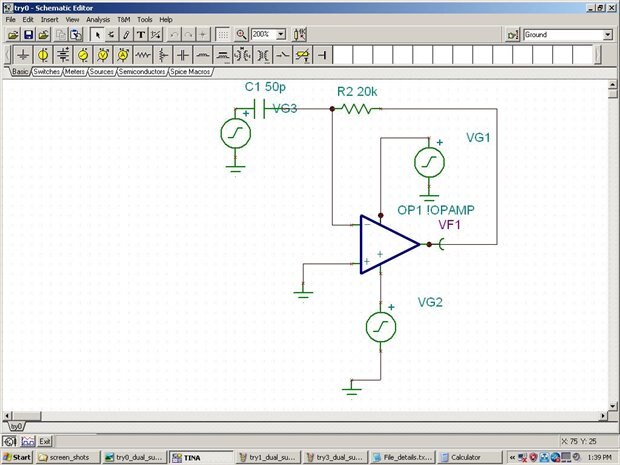
Op-amps in PSOC 4 do not have negative supply terminal. Since, this project needs dual supply op-amp external components LF356 are used. Following circuit gives the differentiator configuration. For integrator the resistor and capacitor placement should be interchanged.


To design the R and C values, simulation has been done in TINA-TI. A freely available tool distributed by Texas Instruments. The second figure gives the differentiator output VF1 for the input at the bottom. Here, R=20K and C=250nF. In the 3rd figure, capacitance is reduced to 50 pF. It can be observed that, proper output is not obtained. For proper output, the capacitor should be in the transient state. In other words the RC time constant should be much greater than the differentiation period. The slew time, 300K in this case, should be much less than the signal variation time. The resistor value should be high enough for low power consumption. The off-time should be much larger than the RC time constant. Otherwise, residual charges creates problem in the successive differentiations. This is not exhibited in the simulation. But it shows in the implementation. The last figure shows the integration output.


image


Rest of the three figures are added in separate blogs. There is a problem in attachment. It is giving an error as file size exceeded 2MB though the file size is only 89KB.

  • Sign in to reply
  • malamitra
    malamitra over 11 years ago

    Please, see post 10  part2 for rest of the figures.

    • Cancel
    • Vote Up 0 Vote Down
    • Sign in to reply
    • More
    • Cancel
element14 Community

element14 is the first online community specifically for engineers. Connect with your peers and get expert answers to your questions.

  • Members
  • Learn
  • Technologies
  • Challenges & Projects
  • Products
  • Store
  • About Us
  • Feedback & Support
  • FAQs
  • Terms of Use
  • Privacy Policy
  • Legal and Copyright Notices
  • Sitemap
  • Cookies

An Avnet Company © 2025 Premier Farnell Limited. All Rights Reserved.

Premier Farnell Ltd, registered in England and Wales (no 00876412), registered office: Farnell House, Forge Lane, Leeds LS12 2NE.

ICP 备案号 10220084.

Follow element14

  • X
  • Facebook
  • linkedin
  • YouTube