


If you like my project vote for "A Smarter Tricopter - Yuri Tikhonov" 
Good day comrades!
As I promised, today we talk about the communication of PSoC 4 with standard MultiWii PC Software. Today the following modules are 90% ready:
- UpTime system.
- System of communication with the receiver (this week I'll fix some bugs).
- UART module for configuration and telemetry.
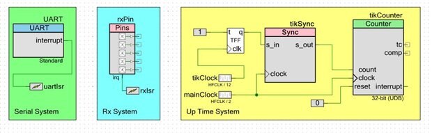
"PSoC schematics" looks like this:
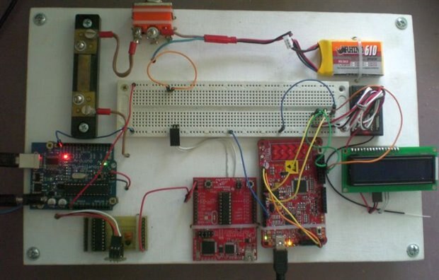
The testing station has not changed and it has the view as follows:
Expectedly, I want to talk about the UART module.
Green: UART communication module works using interrupts. I use two interrupts in a single handler (UART_INTR_TX_EMPTY and UART_INTR_RX_NOT_EMPTY).
Now I only modify MultiWii to work correctly with the PSoC, later I'll make it's optimization.
CY_ISR(serialInterruptHandler) // interrupt
{
    if ( (UART_GetTxInterruptMode() & UART_INTR_TX_EMPTY) != 0 ) // RX interrupt
    {
        UART_ClearTxInterruptSource(UART_INTR_TX_EMPTY); // clear interrupt
        if( headTX != tailTX )
            UART_UartPutChar(bufTX[tailTX++]); // Transmit next byte in the ring
        if ( tailTX == headTX )                // Check if all data is transmitted
            serialIntOff;                      // Disable transmitter interrupt
    }

    if ( (UART_GetRxInterruptMode() & UART_INTR_RX_NOT_EMPTY) != 0 ) // RX interrupt
    {
        UART_ClearRxInterruptSource(UART_INTR_RX_NOT_EMPTY);  // clear interrupt
        if ( UART_SpiUartGetRxBufferSize() < 1) return;
        uint8_t d = UART_UartGetChar();
        UART_SpiUartClearRxBuffer();
        uint8_t i = serialHeadRX[0] + 1;
        if (i != serialTailRX[0])
        {
            serialBufferRX[serialHeadRX[0]][0] = d;
            serialHeadRX[0] = i;
        }
    }
}
To better understand how the code works, here are some explanations:
- as buffers Rx/Tx we use bufTX[] and serialBufferRX[][0] arrays;
- tail and head of this buffers are stored, respectively, in tailTX, serialHeadRX[0], headTX and serialTailRX[0];
- serialIntOff = UART_SetTxInterruptMode(0x00 - disable Tx interrupts);
- serialIntOn = UART_SetTxInterruptMode(UART_INTR_TX_EMPTY) - turn on Tx interrupts (all data was transmitted and hardware Tx buffer is empty);
- UART_INTR_RX_NOT_EMPTY - this interrupt occurs if the input UART read some data.
I would also speak about other functions adapted for the correct work with MultiWii GUI:
1. Adding two byte word in the Tx buffer (unsigned int16):
void serialize16(int16_t a)
{
  bufTX[headTX++]  = a;
  bufTX[headTX++]  = a>>8&0xff;
}
2. Adding one byte word in the Tx buffer (unsigned int8):
void serialize8(uint8_t a)
{
  bufTX[headTX++]  = a;
}
3. Turn on UART transmitting (realy - turn on Tx interrupts):
void UartSendData(void)
{                      // Data transmission acivated when the ring is not empty
  serialIntOn;          // Enable transmitter interrupt
}
4. Activate the data transmission on the UART. In my project I use only one module UART, and only one fixed speed 115200 baud, so variables port and baud temporarily left only for compatibility with MultiWii:
void SerialOpen(uint8_t port, uint32_t baud)
{
  UART_Start();
  uartIsr_StartEx(serialInterruptHandler);
}
5. Turn off UART transmitting (variable port is only for compatibility with MultiWii):
void SerialEnd(uint8_t port)
{
  UART_Stop();
}
6. Reading data via UART. Realy - buffer reading (variable port is only for compatibility with MultiWii):
uint8_t SerialRead(uint8_t port)
{
    uint8_t c = serialBufferRX[serialTailRX[port]][port];
    if ((serialHeadRX[port] != serialTailRX[port])) serialTailRX[port] = serialTailRX[port] + 1;
    return c;
}
7. Checking Rx data availability (variable port is only for compatibility with MultiWii):
uint8_t SerialAvailable(uint8_t port)
{
  return serialHeadRX[port] - serialTailRX[port];
}
8. Transfer one byte via UART (variable port is only for compatibility with MultiWii):
void SerialWrite(uint8_t port,uint8_t c)
{
  serialize8(c);
  UartSendData(); // Serial TX is driven via a buffer and a background intterupt
}
The function of ensuring communication with MultiWii GUI has a name serialCom(), It is currently undergoing a "permanent modifications," because yet I have not IMU, EEPROM, and some other functions.
So, the moment of truth, start of MultiWii GUI:
As you can see, telemetry data is successfully transferred! Reaction to the sticks of radio equipment, fast and accurate, in general I am happy!
Next week I plan to do another small but necessary system: EEPROM. Because without it, store settings and calibration unit is not yet possible.
See you next week!
| # | link | description |
|---|---|---|
| 1 | PSoC 4 Tricopter Part #1 | Introduction |
| 2 | PSoC 4 Tricopter Part #2 | Purchase of components from Farnell and HobbyKing |
| 3 | PSoC 4 Tricopter Part #3 | PSoC firmware: upTime & Rx |
| 4 | PSoC 4 Tricopter Part #4 | PSoC firmware: UART & MultiWii GUI |
| 5 | PSoC 4 Tricopter Part #5 | PSoC firmware: EEPROM emulation |
| 6 | PSoC 4 Tricopter Part #6 | PSoC firmware: Servo & ESC control |
| 7 | PSoC 4 Tricopter Part #7 | PSoC firmware: IMU, LED's & PID |
| 8 | PSoC 4 Tricopter Part #8 | Hardware: PCB |
| 9 | PSoC 4 Tricopter Part #9 | Hardware: tricopter's frame |
| 10 | PSoC 4 Tricopter Part #10 | Hardware: YAW mechanics & motors |
| 11 | PSoC 4 Tricopter Part #11 | Hardware: ESC's, wires & misc |
| 12 | PSoC 4 Tricopter Part #12 | Final: The first fly |
If you like my project vote for "A Smarter Tricopter - Yuri Tikhonov"
Top Comments