


The DAS projects uses an LDR to provide a ambient light feedback. This feedback is used to detect night and day time differences.
This time the LCD came in handy to display the results of the conversion. Although initially there was a issue that the values were in reverse.
In order to sense the LDR properly it needed to be powered up or biased with a current source. To make that we would need a pull-up.
The max value this particular LDR VT90N1LDR VT90N1 could take was 200k while light is completely blocked out.
Hence a current drive > (3.3/200) mA would be enough to run this sensor.
However I had only 100k as the max value available in my bin so I went with that. Effectively the max current would be 11uA min to 33uA max (when LDR is shorted).
This is ok for a I/O pin also. But then while the 100K was a pull up I had one more issue, the ADC value would increase with decrease in light intensity as the LDR resistance would increase.
This would mean the software would need to do a subtraction from the max value again and again at each sample to obtain the real light intensity.
To over come this, I reversed the configuration. So now 100k is a sink instead of a source.
Here is the schematics:
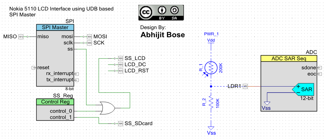
This way both the requirements were met and I am able to use the direct milli-volt reading.
Here is the video showing the LDR operation.
For some strange reason I am unable to embed this video. I was suppose to update this post last week but got delayed due to some more interface issues.
More later..
