


Thank you DAB and Victor for your comments on my previous blog post. This weekend I focused on further processing the electric signals associated to eye movements, which so far I was able to measure using electrodes placed on forehead, amplify, and bring to a window comparator made out of the two op-amps inside the PSoC4 chip.
The first step, I replaced the debouncers blocks that I used for low-pass filtering with glitch filter blocks. The glitch filter blocks provide me a better way of measuring the length of pulses in clock period units. I then sent the output pulses to the CPU for further processing. These output pulses are of two types: 1. Corresponding to eyes movement to the left, and 2. Corresponding to eyes movement to the right.
The program that runs in the CPU receives the left/right (eye movement) pulses, stores them in memory, and then encodes them using a Manchester encoding format. The encoded pulses are then loaded into a shift register, after which they are modulating a 38kHz signal and driven out to an infrared LED.
This encoded signal is compatible with infrared remote control signals, so it can be received and decoded by appliances that have infrared remote control receivers.
Here is a screenshot of the entire system as implemented into the PSoC4 chip on the Pioneer kit:
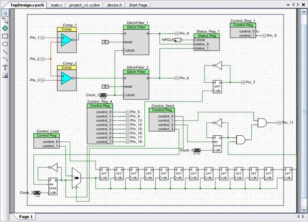
The long chain of flip-flops is my shift register since I ran out of UDBs ( 2 hold the glitch filters, and the other two the registers). So after being a little disappointed when I've got the error message pointing to my PSoC4 shift register block resource availability I then tried to "trick" the chip by creating a "home made" shift register and I was happy to see that it worked.
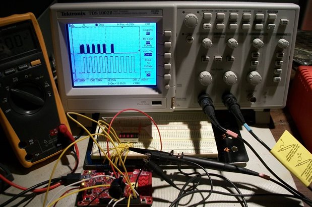
And below I am showing a few examples of data encoding. The picture below shows the Manchester encoding four signals corresponding to sequential eyes movement four times to the left (and back to the center). The encoded signal as stored in a register inside the CPU can be seen on the LED bar graph (on the breadboard). Then the modulated signal transmitted serially through one pin of PSoC4 chip is captured by the oscilloscope (upper trace). The lower trace shows the clock that controls the shift register. In these experiments below I used a much lower frequency for validation/troubleshooting purposes. There is a start bit and an end bit, and in between there are the four Manchester encoded bits corresponding to the eyes movement described above:
The following picture shows the same type of example but this time for a sequence of eye movement: right -> center -> right -> center -> left -> center -> left -> center
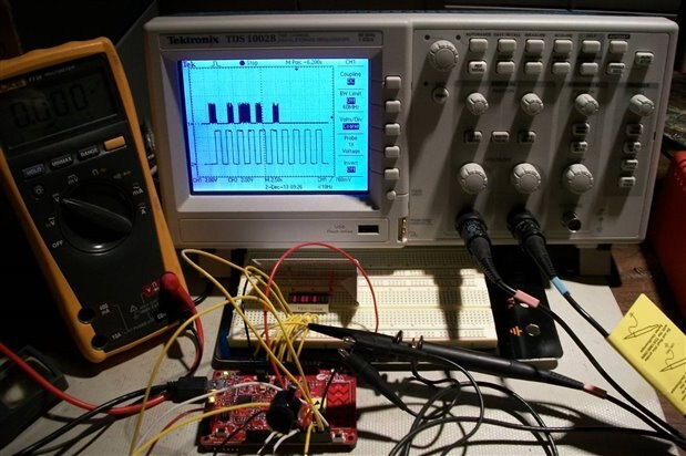
And one more example for a sequence of eye movement: left -> center -> right -> center -> right -> center -> left -> center.

This is where I am now with the project; next step I will add an infrared LED and to try to transmit a code to a receiver. In the mean time I will be designing the PCB that holds the front-end amplifier circuit (which looks now like a mess of wires and prototype breadboards hanging on my forehead, as you could see in the video I posted last week). I’ll post more updates as I get more work done.
Best Wishes,
Cosmin

