


Light Sensor and Backlight Control Demo Video
The following video shows the light sensor readings displayed on the left LCD and Henrietta using the readings to adjust the LCD backlight intensity. There is also an oscilloscope to show the pulse width modulation waveform at various ambient light levels.
http://www.element14.com/community/videos/10809/l/the-henrietta-project--light-sensor
Light
The Henrietta Project uses a $3 cadmium sulfide light sensor module to detect incident light levels. This module has an analog output which is connected to an analog-to-digital converter input on the Pioneer Kit. The signal is simply converted to a percentage of full scale by dividing by 41. The 12 bit A/D converter full scale is 4095, so dividing by 41 ensures the result will always be 99 or less.
Backlight
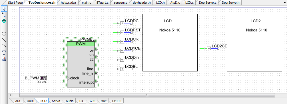
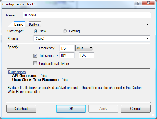
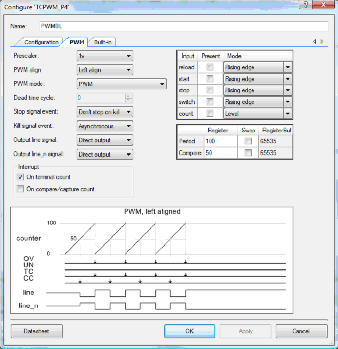
The LCD backlight LEDs take about 48 mA, which is too much for a digital output from the PSoC4, so they are driven by a PNP transistor mounted on the back of one of the LCDs. This transistor is in turn driven by a pulse-width-modulated (PWM) output from the PSoC4.
PWM is very easy to set up in PSoC Creator - these are the relevant screenshots.
Conclusions
Many commercial displays control backlight intensity based on ambient light levels, whether to improve power consumption, reduce eye strain, or simply to make the display adequately visible. This capability is easy to implement with the PSoC4 and it adds a professional feature to the Henrietta project.
Next Steps
I expect my next update to cover the GPS clock in more detail.
For more info on the Henrietta Project, which is entered in the Smarter Life Challenge, check these logs:
