


The Henrietta Project uses a resistive touch screen for user input. This log details how the touch screen portion of the Henrietta Project was implemented.
The touch screen used was a replacement touch screen for a Nintendo DS Lite costing $2.60. The custom interface card cost about $2.
The Theory
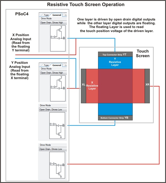
This touch screen has 4 connection strips, one along each side. There are 2 resistive layers, one layer has a connection along its top and bottom edges, the other layer has a connection along the left and right sides.
Location readings are obtained as X-Y coordinates, requiring a separate sequence for each axis. To read a coordinate voltage on the X axis, a voltage is applied across the (X) layer that has left and right connections. When the surface is touched, the X layer contacts the Y layer at that point. The voltage at that point is proportional to how far the point is across the X resistive surface. If the Y layer is not connected to power at this time, its contacts may be used to read the voltage of the touched point on the X layer. Similarly to read the Y coordinate, voltage must be applied across the Y layer (top to bottom connections) and use the left or right connection to read the position-proportional voltage.
This scheme requires each pin connection to be alternately connected to a power rail and an analog input. When the analog input is being read, that pin must be disconnected from all power.
To keep it simple and highlight the flexibility of the PSoC4, this design uses 4 digital output pins to supply power, (2 for each axis) plus 2 analog input pins to read the X and Y positions.
The PSoC4 has flexible output stages so the pin that drives the bottom strip low during a Y read uses an open drain pull-down output stage. When the output is a logic zero, that pin is pulled down, when it is a logic 1, the output is floating. The PSoC4 can also be configured to allow an output stage to only pull-up, so this can be used to drive the top pin on the Y layer. For this configuration, a logic 0 leaves the output floating.
The X layer connections get a corresponding configuration, allowing the PSoC4 to apply power or float pins at appropriate times. The analog inputs are always connected, but only read when the digital outputs they are monitoring are floating.
There are a couple of other issues that need to addressed:
- The resistance across the Nintendo screen is only 300 ohms. This is too much of a load for a digital output, which can only supply 4 mA. To reduce the current drawn by the screen, I put a 560 ohm resistor in series with the high side driver on each layer. This reduces the maximum voltage read by the analog inputs, but the A/D has plenty of resolution to implement a fingertip sized keypad without needing to implement an analog amplifier.
- The electrostatic fields around a human finger can make a floating analog input go wild. Actually, if the inputs are floating there are lots of other stray electric fields that can make it look like the screen is being hammered when there is nothing even nearby physically. After a touch connects layers, the low impedance of the powered layer stops the problem, but as a finger approaches or leaves the surface, the readings may go haywire. To kill this problem, I connected each of the 4 pins to ground with its own 10K resistor. This resistance is low enough to minimize electric field influences but high enough that it doesn't affect the proportional touch voltages significantly.
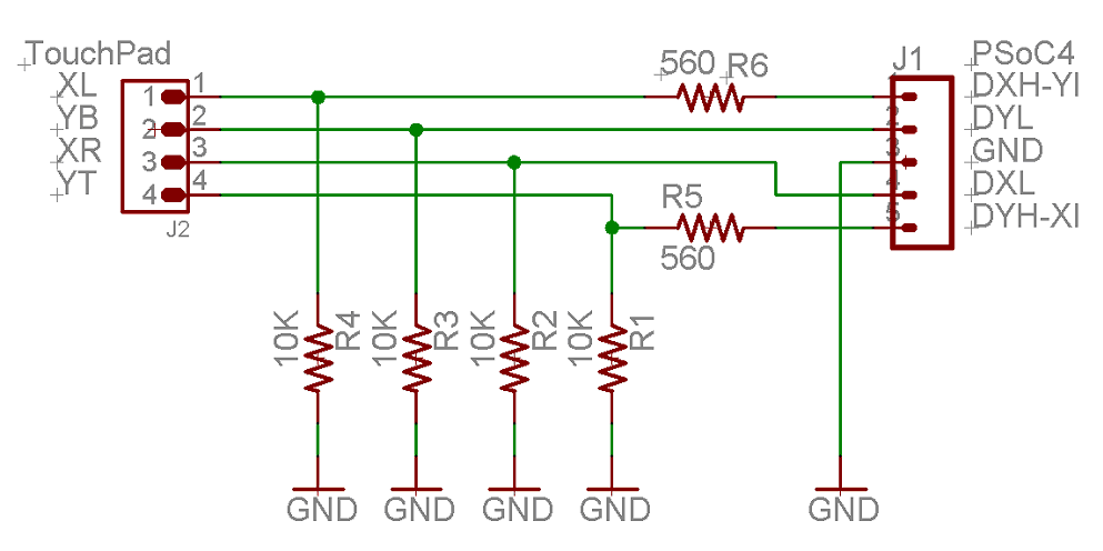
Touch Screen Interface Schematic
The Build
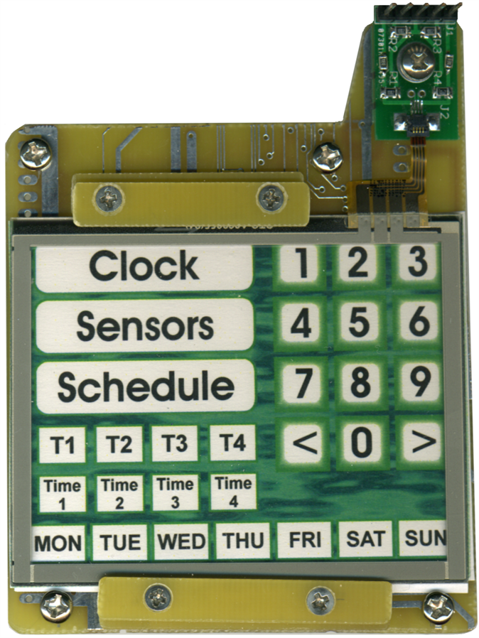
This screen is being used to implement a multi-button keypad with fixed layout and fixed function to provide a more intuitive, less confusing interface than a typical thermostat which might have just 3 context-sensitive multifunction buttons, controlling a multilevel menu structure. The screen is not placed over the display, so your fingers don't obscure or smudge the display and this allows the keypad to have a nice colourful background.
The touch screen is clamped onto a surplus circuit board with the printed keypad layout sandwiched between the Screen and the fibreglass card.
The flex ribbon connection from the screen is plugged into a custom circuit board I made to hold the tiny flex connector and the protection resistors mentioned above. This custom interface card is screwed to the same fibreglass circuit board as the screen to prevent the delicate ribbon from being stressed.
There is no bezel to hide the circuitry as this project is intended to showcase the raw underlying electronics.
http://www.element14.com/community/videos/10850/l/the-henrietta-project--touch-pad
Conclusions
There are many ways to use a touch screen.
The PSoC4 can easily implement a resistive touch screen without needing to purchase a specialized driver chip.
For more info on the Henrietta Project, which is entered in the Smarter Life Challenge, check these logs:
videos
http://www.element14.com/community/videos/10720/l/henrietta-eyes-animation-demo
http://www.element14.com/community/videos/10789/l/the-henrietta-project--bluetooth
http://www.element14.com/community/videos/10808/l/the-henrietta-project--voice-control
http://www.element14.com/community/videos/10809/l/the-henrietta-project--light-sensor
http://www.element14.com/community/videos/10810/l/the-henrietta-project--gps-clock
http://www.element14.com/community/videos/10816/l/the-henrietta-project--speech-recognition
http://www.element14.com/community/videos/10720/l/henrietta-eyes-animation-demo
http://www.element14.com/community/videos/10850/l/the-henrietta-project--touch-pad
http://www.element14.com/community/videos/10854/l/the-henrietta-project--pc-app-operation
http://www.element14.com/community/videos/10851/l/the-henrietta-project--pc-app
