


The Issue
The Henrietta Project uses about 16 modules with connectors and about 108 connections. Using traditional Arduino style prototype jumpers this would definitely end up looking like a plate of coloured spaghetti was dumped on the system, pretty much obscuring the electronic modules underneath. Subsystem connection and system functionality would be indecipherable just from looking at the tangle of wires. Since a spaghetti wiring is not an ideal way to cleanly showcase electronics and system design, an alternative was used.
The Solution
First I wanted to bury the wires out of sight without losing their connectivity information. To accomplish this, I ran the wires under the mounting panel but printed a clean layout of the wiring diagram on top of the panel.
The next decision was to use wire wrap technology to make most interconnections. This technology is old but works well for this application where we want reliable but alterable connections:
- Wire wrap makes at least 24 gas-tight connections at each pin, creating a lower impedance contact than a solder joint or a pin and socket connector.
- Wire wrap is far more reliable than pin and socket technology or even solder. Reliability is important is an application like a thermostat. When using jumpers in a system of this complexity, every time you touch the wire to make a change or rearrange the geometry, you run a risk of pulling something loose. Wire wrap connections, by contrast, cannot be pulled off.
- Wire wrap does not incur problems with cold solder joints, solder balls, or flux
- Wire wrap is easier to modify than solder joints. Jumpers are easy, but the cost of making them easy is less reliability.
- Wire wrap takes up less room that pin and socket jumpers - finding an inexpensive picture frame deep enough to accommodate jumper connector height is problematic. It probably is not obvious from the face-on picture, but all modules are mounted on stand-offs to give a more pronounced 3-D effect in the picture frame.
The Pioneer Kit uses sockets, so I ended up using pins in these sockets because I did not want to risk replacing the sockets them with pin headers.
You can get some idea of how tangled the wiring would look, if it was not buried, by looking at the power distribution forest of pins below the Pioneer Kit.
The picture frame is not shown in this wiring picture since I have not mounted the hinged lid yet, but you can see the arm on the servo motor that will push the lid up.
The Learning Curve
You might notice I added a protection fuse to the system. This is because the 5V power supply module I purchased failed - passing a high voltage to the Pioneer Kit. This caused the Pioneer kit to smoke - actual flames, smoke, zapping sounds and associated horrible smell. I'm not sure if the queasy feeling I got was more from the toxic fumes or from the nasty setback. All quite exciting, but not in a good way. It also fried the servo motor. Still waiting for more protection devices - not anxious to repeat the whole troubleshooting / recovery process along with associated expenses and delays. However, when you push the envelope, the inevitable unexpected results need to be accommodated with grace while learning the lesson and moving forward.
The Results
Here is a picture showing the Henrietta Project all wired up, except for the microphone, which has not arrived yet. Interconnections are printed on the panel to show where the wires under the panel are going. There are very few PSoC4 pins that are not connected. It is a tribute to the PSoC4 that this level of utilization could be achieved, although it still required a lot of meticulous planning and a pretty detailed understanding of the Cypress development process. Those who have indulged in Pioneer Kit or Arduino jumpering probably have a good idea how much cleaner this looks than a typical prototype scenario.
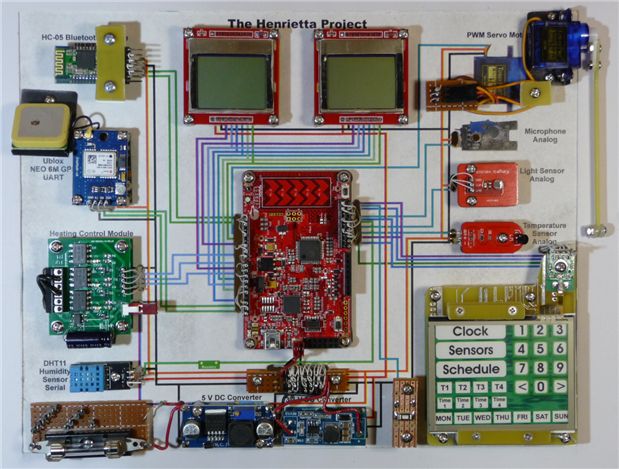
The layout is designed more to showcase capability than optimize performance. For example it is not optimum to place the two antennas so close together and sensors like temperature and humidity should not be enclosed.
All of the modules wired up here are working with test software except the humidity sensor which just arrived. The main issue I have right now is trying to parse the GPS data. Although I can display all of the sensor data from the various modules on the LCDs, I am a long way from mastering the handling of text in C.
Conclusions
Overall, the wire wrap experience was useful and the advantages turned out to be real, although not quite as pronounced as I originally hoped. It did take extra effort to plan and implement, but I would use it again whenever its benefits are needed.
Next Steps
I expect my next update to cover Bluetooth - communicating with my android device, and at the same time will likely demonstrate quite a few of the features of the Henrietta Project.
For more info on the Henrietta Project, which is entered in the Smarter Life Challenge, check these logs:
