element14 Community
element14 Community
    Register Log In
  • Site
  • Search
  • Log In Register
  • Community Hub
    Community Hub
    • What's New on element14
    • Feedback and Support
    • Benefits of Membership
    • Personal Blogs
    • Members Area
    • Achievement Levels
  • Learn
    Learn
    • Ask an Expert
    • eBooks
    • element14 presents
    • Learning Center
    • Tech Spotlight
    • STEM Academy
    • Webinars, Training and Events
    • Learning Groups
  • Technologies
    Technologies
    • 3D Printing
    • FPGA
    • Industrial Automation
    • Internet of Things
    • Power & Energy
    • Sensors
    • Technology Groups
  • Challenges & Projects
    Challenges & Projects
    • Design Challenges
    • element14 presents Projects
    • Project14
    • Arduino Projects
    • Raspberry Pi Projects
    • Project Groups
  • Products
    Products
    • Arduino
    • Avnet & Tria Boards Community
    • Dev Tools
    • Manufacturers
    • Multicomp Pro
    • Product Groups
    • Raspberry Pi
    • RoadTests & Reviews
  • About Us
  • Store
    Store
    • Visit Your Store
    • Choose another store...
      • Europe
      •  Austria (German)
      •  Belgium (Dutch, French)
      •  Bulgaria (Bulgarian)
      •  Czech Republic (Czech)
      •  Denmark (Danish)
      •  Estonia (Estonian)
      •  Finland (Finnish)
      •  France (French)
      •  Germany (German)
      •  Hungary (Hungarian)
      •  Ireland
      •  Israel
      •  Italy (Italian)
      •  Latvia (Latvian)
      •  
      •  Lithuania (Lithuanian)
      •  Netherlands (Dutch)
      •  Norway (Norwegian)
      •  Poland (Polish)
      •  Portugal (Portuguese)
      •  Romania (Romanian)
      •  Russia (Russian)
      •  Slovakia (Slovak)
      •  Slovenia (Slovenian)
      •  Spain (Spanish)
      •  Sweden (Swedish)
      •  Switzerland(German, French)
      •  Turkey (Turkish)
      •  United Kingdom
      • Asia Pacific
      •  Australia
      •  China
      •  Hong Kong
      •  India
      • Japan
      •  Korea (Korean)
      •  Malaysia
      •  New Zealand
      •  Philippines
      •  Singapore
      •  Taiwan
      •  Thailand (Thai)
      • Vietnam
      • Americas
      •  Brazil (Portuguese)
      •  Canada
      •  Mexico (Spanish)
      •  United States
      Can't find the country/region you're looking for? Visit our export site or find a local distributor.
  • Translate
  • Profile
  • Settings
Smarter Life
  • Challenges & Projects
  • Design Challenges
  • Smarter Life
  • More
  • Cancel
Smarter Life
Blog SteadyClip, An Economical Camera Gimbal – Part 03: System Overview
  • Blog
  • Forum
  • Documents
  • Files
  • Events
  • Mentions
  • Sub-Groups
  • Tags
  • More
  • Cancel
  • New
  • Share
  • More
  • Cancel
Group Actions
  • Group RSS
  • More
  • Cancel
Engagement
  • Author Author: jliu83
  • Date Created: 6 Nov 2013 9:28 PM Date Created
  • Views 2236 views
  • Likes 1 like
  • Comments 3 comments
  • steady_clip
  • psoc4
  • smarter_life_challenge
  • smarter_life
Related
Recommended

SteadyClip, An Economical Camera Gimbal – Part 03: System Overview

jliu83
jliu83
6 Nov 2013

Now that we’ve picked out the important parts, it’s time to get a general overview of the project from a systems perspective.  The trick here is to put in the hooks that we need at this stage of the design so that we have access to the critical portions of the system during debug.  As of right now, the system diagram is shown below.

image

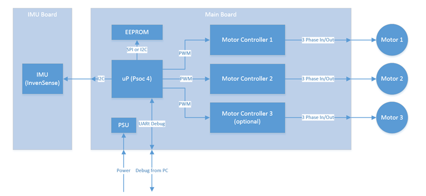
Since the system is rather simple, I will only add a single UART port for debugging.  This port is critical during the tuning of the PID constants.  I will want to be able to change the constants on the fly during runtime, without having to restart the program.  In addition, any errors or log messages can be read through this port. I’ve opted against creating a USB interface due to the time constraint and complexity of the device.  A UART port should give me sufficient information during debug and there are no immediate advantages in using an USB port. It could be argued that the USB port can provide power in addition to debug, but since the device is designed to run independently on battery, the USB bus powered feature is not a necessity. The device could very well require more than the 500 mA at 5V that the USB 2.0 specification allows.  I’ve opted not to include a level shifter for RS232 to reduce cost.  This means that our UART cable must be 3.3V compatible.


I will take a look at the power requirements for the PSU.  I would love to design a switching power supply to provide better efficiencies for all battery output voltages.  The first versions and proof of concept boards might just be a simple LDO.


The EEPROM is added to give the device some non-volatile memory to store calibration data and user settings if needed.  I’m anticipating this need because we might have more complex control schemes in the future and some non-volatile memory is always handy.  The size and electrical interface has not been picked yet.


The connections to the motor drivers are PWM signals.  I will be using PWM blocks in the PSoc 4 for these signals.  Using the PWM blocks should simplify the software aspect of controlling the motors.  Since each motor driver requires 3 PWM signals with specific timing requirements, we might need to customize the PWM blocks for our needs.  Perhaps we can even include some PID control elements in the custom blocks as well.  I’ll dust off the old Verilog book when I find it, as it might be time for a refresher.


Lastly we have the IMU connection through an I2C port.  This should be a simple affair to connect, but the software portion will be the challenge. The InvenSense parts are pretty complex to program and their register maps are gigantic.  I’ll see if I can leverage some work that other people have done to get my program started.


So it looks like we have some work to do.  I need to build the electronics fast, and get a decent mechanical test rig so I can start fine tuning the software.  I think the software will be the most complex part of this device.  As a hardware designer, getting this deep into software is quite a daunting task and I hope I am up for the challenge.

  • Sign in to reply
Parents
  • vsluiter
    vsluiter over 12 years ago

    Hello Jianyi,


    The Invensense document may seem daunting, but it's actually quite easy to set up: select the devices  you want to activate, select the clock you want them to run on and set the range and output data rate. All other features are bonus. This is how most gyraccs work. The 9150 has a lot of features, but you're not forced to use them image

    • Cancel
    • Vote Up 0 Vote Down
    • Sign in to reply
    • More
    • Cancel
  • jliu83
    jliu83 over 12 years ago in reply to vsluiter

    Thanks for the reply.  That gives me some confidence that I will be able to complete the project.

    • Cancel
    • Vote Up 0 Vote Down
    • Sign in to reply
    • More
    • Cancel
Comment
  • jliu83
    jliu83 over 12 years ago in reply to vsluiter

    Thanks for the reply.  That gives me some confidence that I will be able to complete the project.

    • Cancel
    • Vote Up 0 Vote Down
    • Sign in to reply
    • More
    • Cancel
Children
No Data
element14 Community

element14 is the first online community specifically for engineers. Connect with your peers and get expert answers to your questions.

  • Members
  • Learn
  • Technologies
  • Challenges & Projects
  • Products
  • Store
  • About Us
  • Feedback & Support
  • FAQs
  • Terms of Use
  • Privacy Policy
  • Legal and Copyright Notices
  • Sitemap
  • Cookies

An Avnet Company © 2025 Premier Farnell Limited. All Rights Reserved.

Premier Farnell Ltd, registered in England and Wales (no 00876412), registered office: Farnell House, Forge Lane, Leeds LS12 2NE.

ICP 备案号 10220084.

Follow element14

  • X
  • Facebook
  • linkedin
  • YouTube