


In the last post I talked briefly about some features of the RTOS and how it uses time slices. The advantage of time slices is the precision control that I have over the timing of my signals. Instead of using nop delay loops which may or may not unwrap in the correct manner, or timer modules, which have to get set up every time they are used, I can take advantage of the RTOS framework’s API. This simplifies the burden of writing the application code, at the expense of setting up the RTOS. Once the RTOS is set up however, the application code can be developed fairly fast.
State Diagrams and Transitions
So what does a program written for the QP framework look like? Well I’ll illustrate it with an example. After porting the framework, I was able to put together a test program. Below is a state machine of the program that I wanted to write to test out the timing controls, the inputs and the outputs (for the nitpicky RTOS pros, I am not following the UML standard, all the states are just plain Visio boxes).
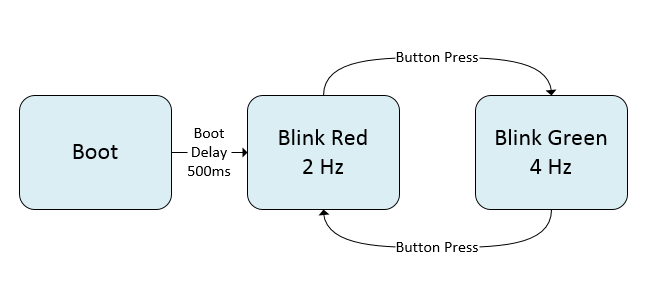
The program is fairly simple, but deals with inputs as well as outputs. The program has 3 states. It boots up, waits for half a second, and then goes into the red LED blinking state. In this state, the red LED blinks at a rate of 2 Hz. If a user button press is detected, the state machine exits the red LED blinking state and enters the green LED blinking state. The green LED blinks at 4 Hz. If the user button is pressed again, the program returns to the red LED blink state.
The Code
Below is the QP representation of the diagram above.
//constructor
void MainFsm_ctor(void) {
  MainFsm *me = &mainFsm_inst; //point state machines to the main object
  QActive_ctor(&me->super, (QStateHandler)&MainFsm_Initial); //instance super, set initial state
  QTimeEvt_ctor(&me->postEveryEvt, POSTEVERY_SIG);
  QTimeEvt_ctor(&me->postInEvt, POSTIN_SIG);
}

//initializer
QState MainFsm_Initial(MainFsm *me, QEvent const *e){
  (void)e;
  QActive_subscribe((QActive *)me, BTN_SIG);

  //reset LED
  me->ledR = LED_OFF;
  me->ledG = LED_OFF;
  me->ledB = LED_OFF;
  LedOut_R_Write(LED_OFF);
  LedOut_G_Write(LED_OFF);
  LedOut_B_Write(LED_OFF);
  return Q_TRAN(&MainFsm_Boot); //initial transition from init pseudostate
}

//wait for all systems to power on, then go into state machine
QState MainFsm_Boot(MainFsm *me, QEvent const *e){
  switch (e->sig) {
    case Q_ENTRY_SIG:
      QTimeEvt_postIn(&me->postInEvt, (QActive *)me, START_DELAY); //start system boot delay
      return Q_HANDLED();

    case POSTIN_SIG:
      return Q_TRAN(&MainFsm_R);

    case Q_EXIT_SIG:
      //reset the timer event
      QTimeEvt_disarm(&me->postInEvt);
      return Q_HANDLED();
  }
  return Q_SUPER(&QHsm_top);
}

//blink red, 2Hz, or alternate output every 250 ms
QState MainFsm_R(MainFsm *me, QEvent const *e){
  switch (e->sig) {
    case Q_ENTRY_SIG:
      QTimeEvt_postEvery(&me->postEveryEvt, (QActive *)me, 250); //post every event signala
      return Q_HANDLED();

    case POSTEVERY_SIG:

      //flip the LED on/off when the timer goes off
      me->ledR = ~(me->ledR);
      LedOut_R_Write(me->ledR);
      return Q_HANDLED();

    case BTN_SIG:
      return Q_TRAN(&MainFsm_G);

    case Q_EXIT_SIG:
      //on exit, turn off the LED
      LedOut_R_Write(LED_OFF);

      //reset the timer event
      QTimeEvt_disarm(&me->postEveryEvt);
    return Q_HANDLED();
  }
  return Q_SUPER(&QHsm_top);
}

//blink red, 4Hz, or alternate output every 125 ms
QState MainFsm_G(MainFsm *me, QEvent const *e){
  switch (e->sig) {
    case Q_ENTRY_SIG:
      QTimeEvt_postEvery(&me->postEveryEvt, (QActive *)me, 125); //post every event signala
      return Q_HANDLED();


    case POSTEVERY_SIG:

      //flip the LED on/off when the timer goes off
      me->ledG = ~(me->ledG);
      LedOut_G_Write(me->ledG);
      return Q_HANDLED();

    case BTN_SIG:
      return Q_TRAN(&MainFsm_R);

    case Q_EXIT_SIG:
      //on exit, turn off the LED
      LedOut_G_Write(LED_OFF);

      //reset the timer event
      QTimeEvt_disarm(&me->postEveryEvt);
      return Q_HANDLED();
  }
  return Q_SUPER(&QHsm_top);
}
The neat thing about using a framework is that you can put snippets of code that executes on state transitions. In the MainFsm_R state for example, the 250 ms timer is activated on state entry. It doesn’t matter if the entry is from the MainFsm_Boot state or the MainFsm_G state, the timer will always turn on.
In the program, I use two different types of timers, the one-shot type and the repeat type. The repeat timers are used to generate the blinking LEDs while the one-shot timer is used for the boot-up delay from MainFsm_Boot.
One of the pitfalls of not using a state machine is that the program tend to turn into spaghetti code. I’m sure everyone’s seen their share of severely nested case statements and if/else trees. By using the structure provided by the QP interface, a very complex state machine can be created without the code turning into a mess. The framework even allows nested states, so that a behavior that is common to several state can be grouped into a single superset state. This way you only need to define the common behavior once, reducing code size and avoiding nesting of flow statements.
The framework itself takes advantage of some of the less used features of the C programming language. The state transitions are handled using cases. The states themselves are functions, and the FSM state is held in memory using a function pointer. Depending on which state the pointer is pointed to, the code inside that function will execute. This is a very clever way organizing code, and allows a level of granularity that is perfect for complex state entries and exits. The programming style is closer to that of higher level languages where events are thrown, then caught, but the whole thing is actually held together in C.
Demo Time
Here’s the program loaded into the PSoC Pioneer kit.
I'll talk about inputs and outputs on the next post.


