element14 Community
element14 Community
    Register Log In
  • Site
  • Search
  • Log In Register
  • About Us
  • Community Hub
    Community Hub
    • What's New on element14
    • Feedback and Support
    • Benefits of Membership
    • Personal Blogs
    • Members Area
    • Achievement Levels
  • Learn
    Learn
    • Ask an Expert
    • eBooks
    • element14 presents
    • Learning Center
    • Tech Spotlight
    • STEM Academy
    • Webinars, Training and Events
    • Learning Groups
  • Technologies
    Technologies
    • 3D Printing
    • FPGA
    • Industrial Automation
    • Internet of Things
    • Power & Energy
    • Sensors
    • Technology Groups
  • Challenges & Projects
    Challenges & Projects
    • Design Challenges
    • element14 presents Projects
    • Project14
    • Arduino Projects
    • Raspberry Pi Projects
    • Project Groups
  • Products
    Products
    • Arduino
    • Avnet Boards Community
    • Dev Tools
    • Manufacturers
    • Multicomp Pro
    • Product Groups
    • Raspberry Pi
    • RoadTests & Reviews
  • Store
    Store
    • Visit Your Store
    • Choose another store...
      • Europe
      •  Austria (German)
      •  Belgium (Dutch, French)
      •  Bulgaria (Bulgarian)
      •  Czech Republic (Czech)
      •  Denmark (Danish)
      •  Estonia (Estonian)
      •  Finland (Finnish)
      •  France (French)
      •  Germany (German)
      •  Hungary (Hungarian)
      •  Ireland
      •  Israel
      •  Italy (Italian)
      •  Latvia (Latvian)
      •  
      •  Lithuania (Lithuanian)
      •  Netherlands (Dutch)
      •  Norway (Norwegian)
      •  Poland (Polish)
      •  Portugal (Portuguese)
      •  Romania (Romanian)
      •  Russia (Russian)
      •  Slovakia (Slovak)
      •  Slovenia (Slovenian)
      •  Spain (Spanish)
      •  Sweden (Swedish)
      •  Switzerland(German, French)
      •  Turkey (Turkish)
      •  United Kingdom
      • Asia Pacific
      •  Australia
      •  China
      •  Hong Kong
      •  India
      •  Korea (Korean)
      •  Malaysia
      •  New Zealand
      •  Philippines
      •  Singapore
      •  Taiwan
      •  Thailand (Thai)
      • Americas
      •  Brazil (Portuguese)
      •  Canada
      •  Mexico (Spanish)
      •  United States
      Can't find the country/region you're looking for? Visit our export site or find a local distributor.
  • Translate
  • Profile
  • Settings
Smarter Life
  • Challenges & Projects
  • Design Challenges
  • Smarter Life
  • More
  • Cancel
Smarter Life
Forum Any ideas on how to count pulses and shut off a PWM
  • Blog
  • Forum
  • Documents
  • Files
  • Events
  • Mentions
  • Sub-Groups
  • Tags
  • More
  • Cancel
  • New
Actions
  • Share
  • More
  • Cancel
Forum Thread Details
  • State Verified Answer
  • Replies 21 replies
  • Answers 1 answer
  • Subscribers 8 subscribers
  • Views 6295 views
  • Users 0 members are here
  • timers
  • pwm
  • counter
  • smarter_life
  • psoc
Related

Any ideas on how to count pulses and shut off a PWM

PaulMakesThings
PaulMakesThings over 11 years ago

TL;DR version: How do I count pulses with programmable digital and use the count to shut off 5 PWMs. The count to shut off and the frequency of the PWMs would have to be set in software for each iteration.


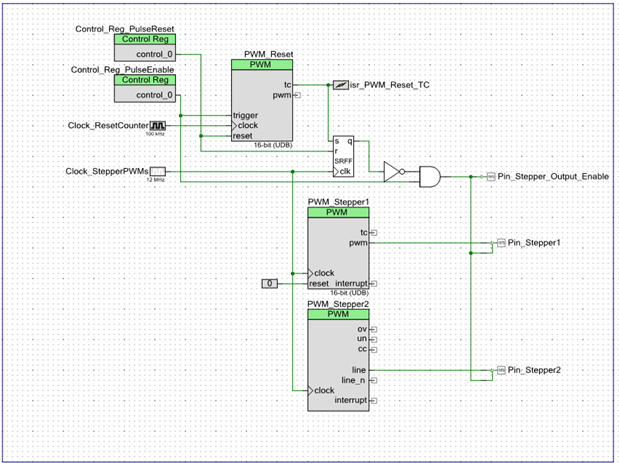
I'm trying to figure out a good way to use programmable digital of the PSoC 4 on the pioneer kit to do coordinated stepper moves. Setting up a PWM module was pretty easy, I just need something to shut it off after a set number of pulses. The black box description is this, the software sets the pulse frequency for several modules, 5 in this case, with the timing already calculated so that they will finish their pulses in the same amount of time, then it starts them at the same time, then they all shut off when they're done and signal (probably via interrupt) back to the software that the move is done and they are ready for the next. I'm thinking the architecture would use one PWM module as the master, if there are not timing glitches they would all finish together, it would stop them, and interrupt that the move was done.


So far I have found that I can easily set a PWM module for a certain frequency from the software, but I'm not sure how to make a counter shut it off. The algorithm is pretty simple for these moves, you have a known speed in pulses at which each axis can move given the electrical and mechanical limitations of the system, given the number of steps required for a move on each axis and that speed you can find which one will take the longest, and divide the number of pulses for all the others to make them happen in that amount of time. At that point most controllers just use timers to generate and count those pulses, I'd like to figure out a nice efficient way to do it in programmable digital. I think it should be pretty simple if I can just figure out how to count pulses with a counter, then I would have it trigger an interrupt and stop the PWMs when the target is reached, can someone show me how to do that? I'd also be interested in other hardware architectures that can do this.


As a note, this is for the smarter life challenge, I'm not really worrying about my competitors seeing my code. If I win I want it to be by making the coolest project, not because they got stuck.


Thanks for reading

  • Sign in to reply
  • Cancel

Top Replies

  • Former Member
    Former Member over 11 years ago +2 verified
    My solution was to use a lower frequency clock to drive a PWM(acting as a counter) just to generate a time-base during which the other 4 PWMs could generate the required number of pulses. We then use a…
  • DAB
    DAB over 11 years ago +1
    Hi Paul, I believe that you can set up counters and status registers inside the PSOC. I think that you can turn the PWM outputs on and off by using a status/control register from the software side. Inside…
Parents
  • Former Member
    0 Former Member over 11 years ago

    My solution was to use a lower frequency clock to drive a PWM(acting as a counter) just to generate a time-base during which the other 4 PWMs could generate the required number of pulses. We then use a bunch of glue logic to gate the signals.


    I only show 2 PWMs below, to demonstrate how it will work with both fixed function PWMs and UDB PWMs.

    image


    #define CLOCK_RESET_KHZ             100     //the input clock for the reset PWM
    #define CLOCK_STEPPER_KHZ           12000   //the input clock for the stepper PWMs
    
    
    #define PULSE_INCREMENT_INTERVAL1   10      //increment pulse1 count by this each time around (minimum of ~10 with these clocks)
    #define PULSE_INCREMENT_INTERVAL2   5       //increment pulse2 count by this each time around
    
    
    #define PULSE_TRAIN_LENGTH_MS       50      //length of time for each co-ordinated move
    
    
    #define SW_DELAY_MS                 100     //delay by this much after starting the co-ordinated move
    
    
    uint8 newMoveFlag = 0xff;
    
    
    int main()
    {
        // Declare variables
        uint16 pulsesPerPeriod1 = 0;
        uint16 pulse1CounterPeriod;
        uint16 pulsesPerPeriod2 = 0;
        uint16 pulse2CounterPeriod;    
        uint16 resetCounterPeriod;
        
        // Start components
        PWM_Stepper1_Start();
        PWM_Stepper2_Start();
        PWM_Reset_Start();
        isr_PWM_Reset_TC_Start();
        
        // Set reset counter period (this could change at runtime also)
        resetCounterPeriod = (CLOCK_RESET_KHZ * PULSE_TRAIN_LENGTH_MS);
        PWM_Reset_WritePeriod(resetCounterPeriod);    
        
        CyGlobalIntEnable; /* Uncomment this line to enable global interrupts. */
        for(;;)
        {
            // Only update the configuration if a new co-ordinated move is desired. 
            // This flag is set in the PWM_Reset TC ISR
            if(newMoveFlag)
            {
                // Calculate the new PWM periods
                // Stepper 1
                pulsesPerPeriod1 += PULSE_INCREMENT_INTERVAL1;
                pulse1CounterPeriod = ((uint32)CLOCK_STEPPER_KHZ/CLOCK_RESET_KHZ)* resetCounterPeriod / pulsesPerPeriod1;
                if(pulse1CounterPeriod < 2) // Check for rollover
                {
                    pulsesPerPeriod1 = PULSE_INCREMENT_INTERVAL1;
                    pulse1CounterPeriod = ((uint32)CLOCK_STEPPER_KHZ/CLOCK_RESET_KHZ)* resetCounterPeriod / pulsesPerPeriod1;
                }
                // Stepper 2
                pulsesPerPeriod2 += PULSE_INCREMENT_INTERVAL2;
                pulse2CounterPeriod = ((uint32)CLOCK_STEPPER_KHZ/CLOCK_RESET_KHZ)* resetCounterPeriod / pulsesPerPeriod2;
                if(pulse2CounterPeriod < 2) // Check for rollover
                {
                    pulsesPerPeriod2 = PULSE_INCREMENT_INTERVAL2;
                    pulse2CounterPeriod = ((uint32)CLOCK_STEPPER_KHZ/CLOCK_RESET_KHZ)* resetCounterPeriod / pulsesPerPeriod2;
                }
                
                // Disable the counters
                Control_Reg_PulseEnable_Write(0x00);
    
    
                // Reset the counters
                Control_Reg_PulseReset_Write(0xff);
                Control_Reg_PulseReset_Write(0x00);
                
                // Set the period of the pulse counters
                // Stepper 1 (UDB PWM)
                PWM_Stepper1_WritePeriod(pulse1CounterPeriod);
                PWM_Stepper1_WriteCompare(pulse1CounterPeriod/2);
                PWM_Stepper1_WriteCounter(0);
                // Stepper 2 (Fixed Function TCPWM)
                PWM_Stepper2_WritePeriod(pulse2CounterPeriod);
                PWM_Stepper2_WriteCompare(pulse2CounterPeriod/2);
                PWM_Stepper2_WriteCounter(0);
                
                // Enable the counters. pulses start here.
                Control_Reg_PulseEnable_Write(0xff);
                
                // Clear the flag and wait for the next update
                newMoveFlag = 0x00;
            }
                
        }
    }
    
    
    /* [] END OF FILE */

    • Cancel
    • Vote Up +2 Vote Down
    • Sign in to reply
    • Reject Answer
    • Cancel
Reply
  • Former Member
    0 Former Member over 11 years ago

    My solution was to use a lower frequency clock to drive a PWM(acting as a counter) just to generate a time-base during which the other 4 PWMs could generate the required number of pulses. We then use a bunch of glue logic to gate the signals.


    I only show 2 PWMs below, to demonstrate how it will work with both fixed function PWMs and UDB PWMs.

    image


    #define CLOCK_RESET_KHZ             100     //the input clock for the reset PWM
    #define CLOCK_STEPPER_KHZ           12000   //the input clock for the stepper PWMs
    
    
    #define PULSE_INCREMENT_INTERVAL1   10      //increment pulse1 count by this each time around (minimum of ~10 with these clocks)
    #define PULSE_INCREMENT_INTERVAL2   5       //increment pulse2 count by this each time around
    
    
    #define PULSE_TRAIN_LENGTH_MS       50      //length of time for each co-ordinated move
    
    
    #define SW_DELAY_MS                 100     //delay by this much after starting the co-ordinated move
    
    
    uint8 newMoveFlag = 0xff;
    
    
    int main()
    {
        // Declare variables
        uint16 pulsesPerPeriod1 = 0;
        uint16 pulse1CounterPeriod;
        uint16 pulsesPerPeriod2 = 0;
        uint16 pulse2CounterPeriod;    
        uint16 resetCounterPeriod;
        
        // Start components
        PWM_Stepper1_Start();
        PWM_Stepper2_Start();
        PWM_Reset_Start();
        isr_PWM_Reset_TC_Start();
        
        // Set reset counter period (this could change at runtime also)
        resetCounterPeriod = (CLOCK_RESET_KHZ * PULSE_TRAIN_LENGTH_MS);
        PWM_Reset_WritePeriod(resetCounterPeriod);    
        
        CyGlobalIntEnable; /* Uncomment this line to enable global interrupts. */
        for(;;)
        {
            // Only update the configuration if a new co-ordinated move is desired. 
            // This flag is set in the PWM_Reset TC ISR
            if(newMoveFlag)
            {
                // Calculate the new PWM periods
                // Stepper 1
                pulsesPerPeriod1 += PULSE_INCREMENT_INTERVAL1;
                pulse1CounterPeriod = ((uint32)CLOCK_STEPPER_KHZ/CLOCK_RESET_KHZ)* resetCounterPeriod / pulsesPerPeriod1;
                if(pulse1CounterPeriod < 2) // Check for rollover
                {
                    pulsesPerPeriod1 = PULSE_INCREMENT_INTERVAL1;
                    pulse1CounterPeriod = ((uint32)CLOCK_STEPPER_KHZ/CLOCK_RESET_KHZ)* resetCounterPeriod / pulsesPerPeriod1;
                }
                // Stepper 2
                pulsesPerPeriod2 += PULSE_INCREMENT_INTERVAL2;
                pulse2CounterPeriod = ((uint32)CLOCK_STEPPER_KHZ/CLOCK_RESET_KHZ)* resetCounterPeriod / pulsesPerPeriod2;
                if(pulse2CounterPeriod < 2) // Check for rollover
                {
                    pulsesPerPeriod2 = PULSE_INCREMENT_INTERVAL2;
                    pulse2CounterPeriod = ((uint32)CLOCK_STEPPER_KHZ/CLOCK_RESET_KHZ)* resetCounterPeriod / pulsesPerPeriod2;
                }
                
                // Disable the counters
                Control_Reg_PulseEnable_Write(0x00);
    
    
                // Reset the counters
                Control_Reg_PulseReset_Write(0xff);
                Control_Reg_PulseReset_Write(0x00);
                
                // Set the period of the pulse counters
                // Stepper 1 (UDB PWM)
                PWM_Stepper1_WritePeriod(pulse1CounterPeriod);
                PWM_Stepper1_WriteCompare(pulse1CounterPeriod/2);
                PWM_Stepper1_WriteCounter(0);
                // Stepper 2 (Fixed Function TCPWM)
                PWM_Stepper2_WritePeriod(pulse2CounterPeriod);
                PWM_Stepper2_WriteCompare(pulse2CounterPeriod/2);
                PWM_Stepper2_WriteCounter(0);
                
                // Enable the counters. pulses start here.
                Control_Reg_PulseEnable_Write(0xff);
                
                // Clear the flag and wait for the next update
                newMoveFlag = 0x00;
            }
                
        }
    }
    
    
    /* [] END OF FILE */

    • Cancel
    • Vote Up +2 Vote Down
    • Sign in to reply
    • Reject Answer
    • Cancel
Children
  • PaulMakesThings
    0 PaulMakesThings over 11 years ago in reply to Former Member

    Awesome, thank you! I'll dig into this when I get home. It looks great. First thing I'll need to do is read the datasheet on that SRFF component, I don't know what that is.

    • Cancel
    • Vote Up 0 Vote Down
    • Sign in to reply
    • Verify Answer
    • Cancel
  • Former Member
    0 Former Member over 11 years ago in reply to PaulMakesThings

    The SRFF is a set-reset flip flop. It basically remembers a value (Q) that is set to 1 when set (S) is high and a positive clock edge occurs, and is reset to 0 when when reset (R) is high and a positive edge occurs. If set (S) is low and a clock edge occurs, the previous value of Q is maintained.


    We are using it to "latch" (remember) the TC value from the reset PWM.


    Here's the useful truth table from the datasheet:


    image

    • Cancel
    • Vote Up 0 Vote Down
    • Sign in to reply
    • Verify Answer
    • Cancel
  • PaulMakesThings
    0 PaulMakesThings over 11 years ago in reply to Former Member

    I see, so it just carries through unless it is set high or reset low. That will be very useful in general.

    • Cancel
    • Vote Up 0 Vote Down
    • Sign in to reply
    • Verify Answer
    • Cancel
  • hlipka
    0 hlipka over 11 years ago in reply to Former Member

    Since a PWM is just a counter in disguise (see the PSoC TCPWM component...), its a quite simple and neat solution.

    • Cancel
    • Vote Up 0 Vote Down
    • Sign in to reply
    • Verify Answer
    • Cancel
element14 Community

element14 is the first online community specifically for engineers. Connect with your peers and get expert answers to your questions.

  • Members
  • Learn
  • Technologies
  • Challenges & Projects
  • Products
  • Store
  • About Us
  • Feedback & Support
  • FAQs
  • Terms of Use
  • Privacy Policy
  • Legal and Copyright Notices
  • Sitemap
  • Cookies

An Avnet Company © 2025 Premier Farnell Limited. All Rights Reserved.

Premier Farnell Ltd, registered in England and Wales (no 00876412), registered office: Farnell House, Forge Lane, Leeds LS12 2NE.

ICP 备案号 10220084.

Follow element14

  • X
  • Facebook
  • linkedin
  • YouTube