Table of contents
Abstract
Building a DIY pick and place machine that is good for small hobbyist projects!
Project
Building Your Own DIY Pick-and-Place Machine
In this blog we’ll explore how to build a DIY pick-and-place machine using commonly available parts and an Nvidia Jetson for the brains.
The Concept
This build borrows concepts from DIY 3D printers. However, instead of a hot end for extrusion, we’ll attach a vacuum pump end for picking up and placing parts on a PCB. The project is designed to be modular, precise, and relatively low-cost compared to commercial pick-and-place machines.
The Build
-
Axes and Motion
- Z-Axis: The Z-axis will be driven by two motors, each paired with an M8 lead screw. This design ensures stability and precise vertical movement for picking and placing components.
- X and Y Axes: These axes will use single motors paired with GT2 tracks and pulleys. This setup is reliable and widely used in the 3D printing world for smooth, controlled motion.
-
Part Handling
The vacuum pump end replaces the traditional hot end. It will pick up components via suction and release them accurately onto the PCB. -
Motor Control
- Z-Axis Motors: Controlled by the TMC5272-EVAL-KIT, which offers smooth and precise movement.
- X and Y Axes: Driven by the Infineon BTN8982TA motor drivers, ensuring efficient and reliable operation.
-
Brains and Vision
The machine will be powered by an Nvidia Jetson Nano, connected to a Pi Camera. The Jetson’s AI capabilities will handle:- Object Recognition and Detection: Identifying components to pick.
- Alignment: Ensuring parts are placed accurately on the PCB.
Why Build This?
Building your own pick-and-place machine allows you to customize the machine to your needs, learn about robotics and AI, and save money compared to commercial options. Whether you’re a hobbyist or a professional looking for a DIY solution, this project will challenge your engineering skills and bring automation into your workshop.
Stay tuned, and happy making!
Project Genesis: Modifying the Green Mamba v2.0
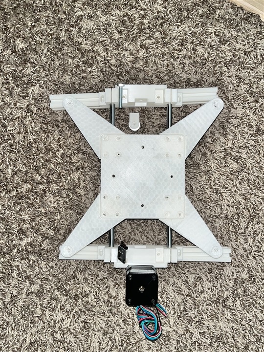
Every great project starts with a solid foundation, and my DIY Pick and Place Machine is no exception. I began by repurposing the Green Mamba v2.0 DIY 3D Printer design as the structural blueprint for my machine. This versatile base provides an excellent starting point for creating a custom pick and place system.
Structural Components: 3D Printed Aluminum Extrusion Mounts
The frame came together through careful modification of the original Green Mamba design, with a focus on 3D printing mounts for 2020 aluminum extrusion. These precision-printed components allow for a robust and customizable frame that can be precisely adjusted to meet the specific requirements of a pick and place machine.
Axis Configuration
The machine's frame is built around three primary axes:
- Y-axis:
- 2 Guide Rails
- TX2 Pulley
- 1 Nema17 Motor
- X-axis:
- 2 Guide Rails
- TX2 Pulley
- 1 Nema17 Motor
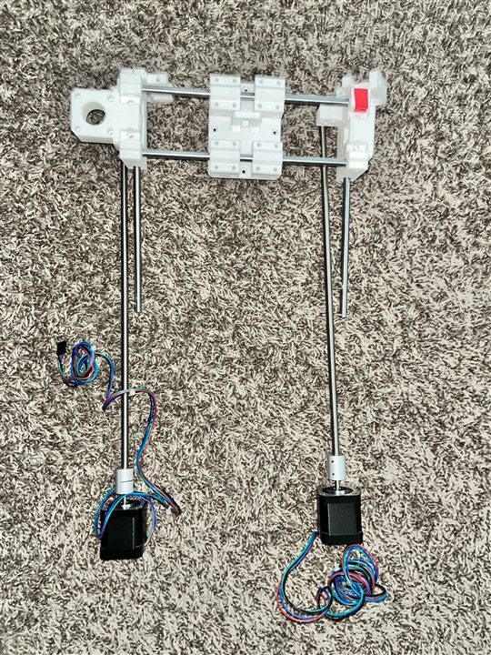
- Z-axis:
- 2 Guide Rails
- 2 Lead Screws
- 2 Nema17 Motors


Challenges and Modifications
No DIY project comes without its challenges, and this build is no exception. I encountered a critical issue with the lead screws and T-nuts that required some creative problem-solving. The 400mm lead screw worked perfectly with the T-nuts, but the 200mm lead screw I initially purchased didn't align as expected.
Adaptation Strategy
- Identified mismatched lead screw dimensions
- Explored alternative mounting solutions
- Developed custom modifications to ensure precise axis movement
Next Steps in the Build
Electronics Integration
The next phase of the project involves:
- Wiring up the electronic components
- Configuring motor connections
- Calibrating the axis movements
Motor Programming
A critical step in bringing the machine to life is programming the motors to understand and navigate the X-Y-Z planes. This involves:
- Developing precise movement algorithms
- Calibrating step sizes and movement accuracies
- Ensuring repeatable and consistent positioning
Image Recognition Development
Looking ahead, the ultimate goal is to implement image recognition capabilities:
- Designing algorithms for component identification
- Creating a machine vision system
- Developing pick and place coordination code
Hardware Setup
The current implementation uses a combination of different motor drivers to control our three axes:
- X/Y axes: TMC5272 stepper motor driver (via SPI)
- Z axis: L298N H-bridge motor driver
- Vacuum control: Infineon DC Motor Shield (to be implemented)
The wiring configuration is straightforward:
TMC5272 Connections:
- SPI1_MISO -> Arduino MISO
- SPI1_MOSI -> Arduino MOSI
- SPI1_SCK -> Arduino SCK / SDA1
- SPI1_CSN -> Arduino D10

L298N Connections:
- IN1 -> Arduino D6
- IN2 -> Arduino D7
- IN3 -> Arduino D8
- IN4 -> Arduino D9
Software Implementation
The code is structured to handle three main components: initialization, motor control, and serial command processing. Let's break down each part:
TMC5272 Configuration
The TMC5272 stepper driver is configured via SPI communication. The initialization process includes:
1. Setting up the internal reference voltage
2. Configuring the chopper parameters
3. Setting current limits for both holding and running states
4. Initializing position mode for precise movements
void initTMC5272() {
    writeTMC5272(GCONF, 0x00000004); // Enable internal reference voltage
    writeTMC5272(CHOPCONF, 0x000100C3); // Standard chopper config
    writeTMC5272(IHOLD_IRUN, 0x00071703); // Set current values
    writeTMC5272(RAMPMODE, 0); // Position mode
    writeTMC5272(XACTUAL, 0); // Reset position
}
Movement Control
The system implements three movement functions:
- `moveX()` - Controls X-axis movement using the TMC5272
- `moveY()` - Similar to X-axis control (to be fully implemented)
- `moveZ()` - Controls Z-axis movement using the L298N
The X and Y axes use precise position control with the TMC5272, which handles acceleration and microstepping internally. The movement is calculated based on physical parameters:
const float mmPerStep = 0.02; // Lead screw pitch divided by steps
The Z-axis implementation uses a standard stepper sequence through the L298N driver:
void moveZ(int direction, int steps) {
    const int stepDelay = 2; // Controls movement speed
    // Implements standard 4-step sequence for bipolar stepper motor
    // ...
}
Command Interface
The current implementation includes a simple serial command interface for testing:
- 'x' - Move X axis 10mm
- 'y' - Move Y axis 10mm
- 'u' - Move Z axis up 200 steps
- 'd' - Move Z axis down 200 steps
Next Steps
The next phase will involve implementing the vacuum control system using the Infineon DC Motor Shield. This will handle the pick-and-place head's vacuum pump for component handling. Additionally, I'll be working on expanding the movement system to include:
- Proper acceleration profiles
- Home position sensing
- Component position calibration
- Integration with a computer vision system
Holiday Update
Quick note: Due to upcoming holiday travels, progress will be minimal in the following week. But don't worry - development will resume at full speed once I'm back! Sometimes we all need a break to come back with fresh ideas and renewed energy.

