


Title: Total Player Monitoring
By: Md. Kamrul Hussain
Project Category: Design Challenge
Project Name: Sudden Impact Wearables Design Challenge
Project duration: Dec01, 2014 to March 27, 2015
Blog post: 02 Week: 02 Time period: Dec04 - Dec10, 2014
Intro:
In this blog post I have shown the ECG signals I have got from the analog front end circuit, presented in my previous blog post [Part1.1]. The ECG signals were measured for different LEAD configurations with different arrangements. The outputs revealed that the proposed arrangement mentioned in Part1.1 can be used for measuring ECG of an athlete or player without causing much discomfort.
Different LEAD combinations:
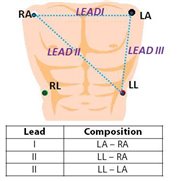
LEAD I for ARRANGEMENT 01:
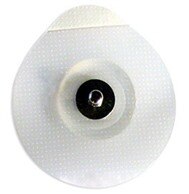


(a) Ag-AgCl electrode (b) LEAD I configuration (c) ECG output for conventional LEAD arrangement 01
One time / single use ECG electrodes from 'TOP TRACE' were used in experimental purpose. It has Ag-AgCl [silver-silver chloride] electrode with adhesive gel for skin-electrode coupling to provide good contact. Though Ag-AgCl has a little health issue for longer use, but it's only for experiment. I would like to go for carbon electrodes in my final design if it's possible.
For LEAD I configuration, the conventional LEAD arrangement produces an output of about 0.6 Vp-p. The resultant signal has 50 Hz [in my country] component contributed by the body [common mode signal] and the mains ground of the oscilloscope and hence the computer. In real life the 50 Hz component will be less as because the whole system will be driven by battery power supply and there will be less 50 Hz interference in an open playground. However, a digital filter can be implemented in the software end, but we'll lose information [like P wave will be flattened]. It's not a diagnosis purpose ECG and a very few amount of information can be found by only one LEAD. So, considering that the detailed wave shape is not much important here, we can implement digital filter if it's necessary later on.
LEAD I for ARRANGEMENT 02:


(a) ECG output of LEAD I for conventional LEAD arrangement 02 (b) LEAD I configuration arrangement 02
For this arrangement, the electrodes are placed too closed to RLD or the reference of Einthoven's triangle, which results an ECG output with slightly different shape for T wave and comparatively reduced QRS complex. However, the overall peak to peak voltage is increased from 0.6 Vp-p for arrangement 01 to about 2 Vp-p for arrangement 02.
Both the arrangements are conventional and produce acceptable output. But as I mentioned in my previous blog [Part1.1] that these arrangements have some issues with controlling the ball with chest, flexibility etc. I'll be experimenting with my proposed arrangement to see whether it produces an acceptable signal in comparison to the other arrangements.
LEAD II for ARRANGEMENT 03:


(a) ECG output of LEAD II for proposed LEAD arrangement 03 (b) LEAD II configuration, arrangement 03
For this arrangement, the RLD [reference] and Left Leg [non-inverting] electrodes are shifted up to the waist and placed side by side where the inverting electrode is connected to the Right Arm to form a LEAD II combination. I am not recalling the mounting part as it was mentioned already in my previous blog [Part1.1].
Now, it seems we have a pretty good signal comparing with the other two. As it was predicted before to have a reduced voltage due to abdominal fat, but it seems that we are having higher QRS complex for this arrangement than the conventional ones. The ECG signal has an output of about 2.5 Vp-p. This could be because I use to have a higher LEAD II than LEAD I in general  .
.
However, the output seems to have high 50 Hz component. If we look into the spectrum view -
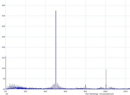
We can see the high 50 Hz component. There is a spike at a very low frequency corner [about 1Hz] which represents the Beats [about 60-80 beats per minute]. The spectrum shows that we have other frequency components upto 100 Hz which is expected for an ECG signal.
In this part I would like to check the output of the bio-amp in case of body movement. As the instrumentation amplifier was not AC coupled and there is no LEAD off detection, the output goes up to the rail in case of sudden big movement.


(a) Output for body movements (b) Spectrum view of the ECG output for body movements
In spectrum view we can observe that there are several high outputs in between 2 Hz to 10 Hz due to the body movement. This can be solved by using the 2nd order high pass filter and fast recovery option featured in the AD8232 Analog Front End.
Result:
The output of the LEAD II for proposed arrangement shows that it can be implemented in this design. So, my next target will be checking the performance of AD8232 with this configuration and implementing the other features like fast recovery, LEAD off detection etc. But for that I have to wait till I get the evaluation kit. During this period I would like to work on sending the captured ECG through a bluetooth module to another controller and to check whether it can be recovered again efficiently.